
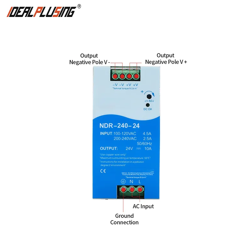
I. APPLICATION
Industrial control system | Semiconductor manufacturing equipment |
Factory automation | Electromechanical Equipment |
II. FEATURES
1 | Protection type: Short circuit/over load/over voltage/over temperature |
2 | Natural air cooling |
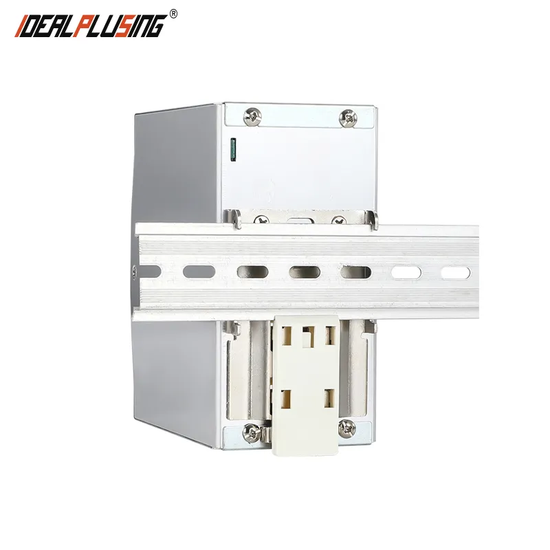
3 | Can be installed on TS-35/7.5 or 15 |
4 | EN61000-6-2 (EN50082-2) Industrial Immunity |
5 | 100% full load aging |
III. DESCRIPTION
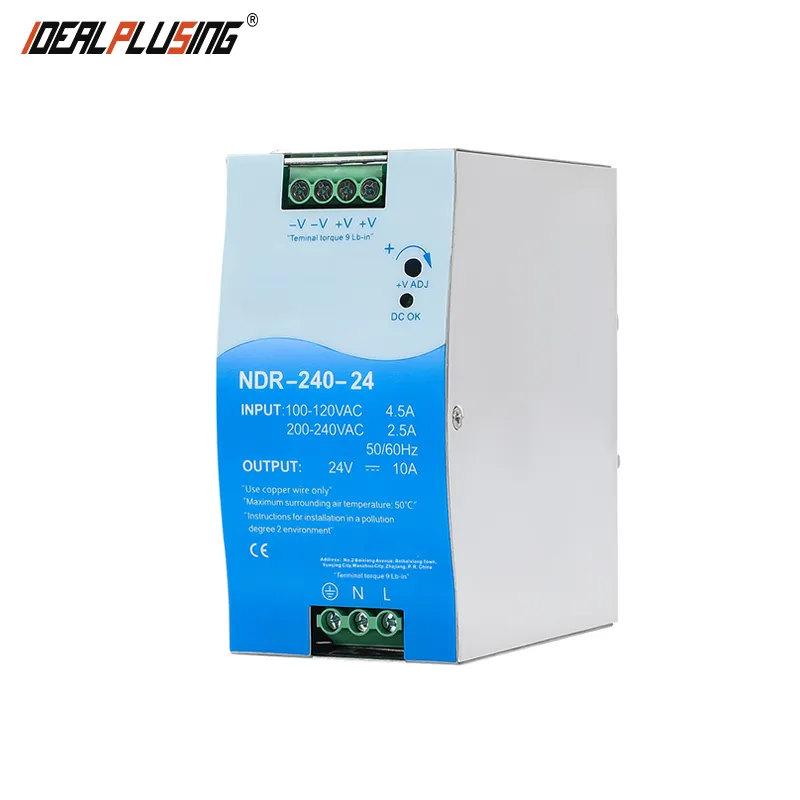
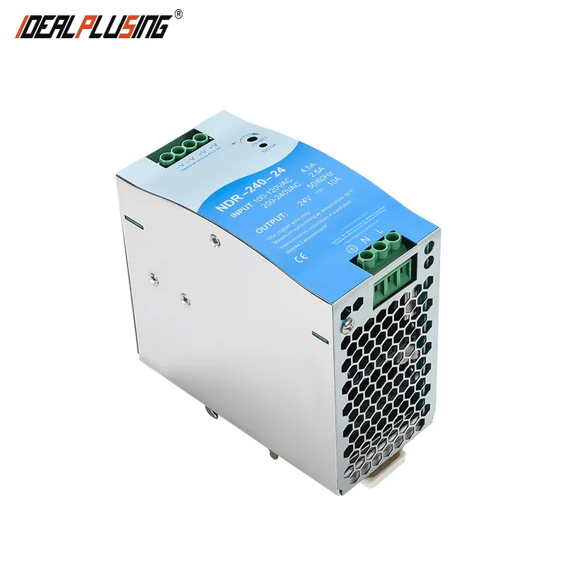
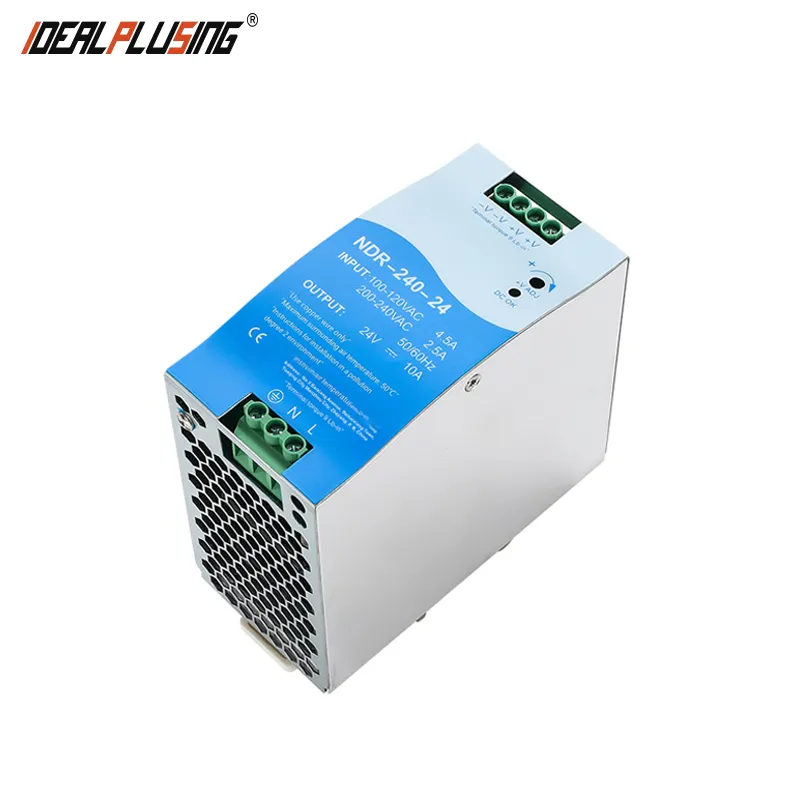
The NDR-240 is designed with a metal casing, which is convenient for improving the heat dissipation consumption of the machine. The working efficiency is up to 89%. Under air circulation conditions, the entire series can work in ambient temperatures ranging from -20 ℃ to 70 ℃. It has a constant current mode overload protection function, suitable for various inductive or capacitive load applications. The complete protection function and industrial control equipment comply with GB4943 certification.
IV. ELECTRICAL SPECIFICATIONS
Model | NDR-240-24 | NDR-240-48 | |
Output | DC voltage | 24V | 48V |
Rated current | 10A | 5A | |
Current range | 0~10A | 0~5A | |
Rated power | 240W | 240W | |
Ripple and noise (maximum) Note 2 | 150mVp-p | 150mVp-p | |
Voltage adjustment range | 24 ~ 28V | 48 ~ 55V | |
Voltage accuracy note 3 | ±1.0% | ±1.0% | |
Linear adjustment rate | ±0.5% | ±0.5% | |
Load adjustment rate | ±1.0% | ±1.0% | |
Start and rise time | 1500ms , 100ms/230VAC & 3000ms , 100ms/115VAC (At full load) | ||
Hold time (Typ.) | 28ms/230VAC & 22ms/115VAC(At full load) | ||
Input | Voltage range | 209~245VAC | |
Frequency range | 47 ~ 63Hz | ||
Efficiency (Typ.) | 89% | 90% | |
AC current (Typ.) | 2.5A/115VAC 1.3A/230VAC | ||
Surge current (Typ) | 20A/115VAC 35A/230VAC | ||
Leakage current | <1mA/ 240VAC | ||
Protection function | Over load | 105% to 130% of rated output power | |
Protection mode: Constant current mode, which can automatically recover after removing abnormal load conditions | |||
Over voltage | 29 ~ 33V | 56 ~ 65V | |
Protection mode: Turn off the output and resume normal output after power restart | |||
Over Temperature | Turn off the output and resume normal output after power restart | ||
Environment | operation temperature | -20~+70℃ (Please refer to the "Derating Curve") | |
Working humidity | 20 ~ 95% RH , No condensation | ||
Storage temperature and humidity | -40 ~ +85℃ , 10 ~ 95% RH | ||
temperature coefficient | ±0 .03%/℃ (0~50℃) | ||
Vibration | Component: 10~500Hz, 2G 10 minutes/cycle, X, Y, Z each 60 minutes; Installation: Compliant withIEC60068-2-6 | ||
Safety regulations and electromagnetic compatibility | Safety regulations | conform to GB4943 | |
pressurization | I/P-O/P:3KVAC I/P-FG:2KVAC O/P-FG:0 .5KVAC | ||
Insulation impedance | I/P-O/P , I/P-FG , O/P-FG:>100M Ohms / 500VDC / 25℃/ 70% RH | ||
Electromagnetic compatibility emission | Conform to EN55032 (CISPR32) , EN61204-3 Class B , EN61000-3-2 ,-3 , EAC TP TC 020 ,CNS13438 | ||
Electromagnetic compatibility immunity | conform to EN61000-4-2,3,4,5,6,8, 11, EN55024, EN61000-6 2 (EN50082-2), EN61204-3,A Grade heavy industry standard, EAC TP TC 020 | ||
Others | MTBF | ≥230 .2K hrs . MIL- HDBK-217F (25℃) | |
Size | 63*125.2*113.5 (MM) | ||
Package | 0.75Kg | ||
Notes | 1. Unless otherwise specified, all specifications and parameters are measured at 230VAC input, rated load, and 25 ℃ ambient temperature. 2. Ripple and noise measurement method: Use a 12 "twisted pair with terminals connected in parallel with 0.1uf and 47uf capacitors, and measure at a bandwidth of 20MHZ. 3. Accuracy: including setting error, linear adjustment rate, and load adjustment rate. 4. The power supply should be considered as a part of the internal components of the system, and electromagnetic compatibility related confirmation should be conducted in conjunction with the terminal equipment. 5. Installation distance: When permanently loaded with full power, it is recommended to have a top distance of 40mm and a bottom distance of about 20mm, with a distance of 5mm on both sides. If the adjacent equipment is a heat source, the recommended space distance is 15mm. 6. Under low input voltage, it is necessary to derate the output. Please refer to the derating curve for details. 7. When the altitude exceeds 2000 meters (6500 feet), the ambient temperature of the fanless model decreases in proportion every 3.5 ℃/1000m, while the ambient temperature of the fanned model decreases in proportion every 5 ℃/1000m. | ||


