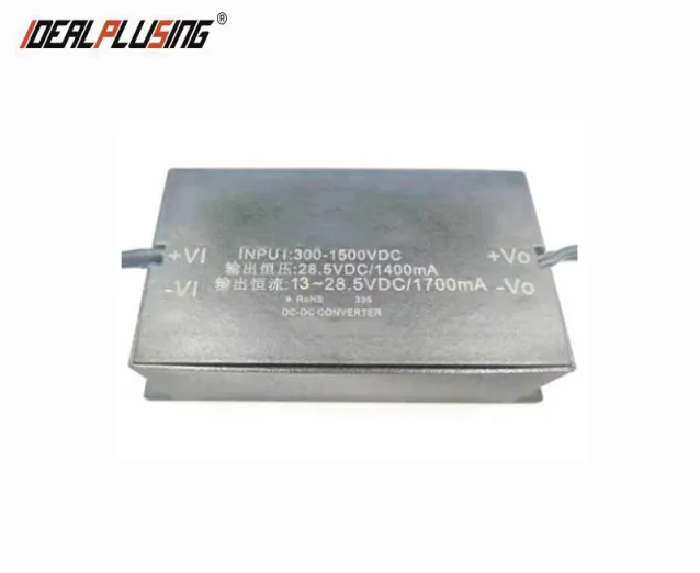

INTRODUCE
A DC/DC high voltage input power supply is a device that converts a high voltage DC power supply into a DC power supply of a different voltage level. They are widely used in a variety of applications
FEATURES
lAC/DC voltage input:300-1500VDC
lHigh reliability, long life, industrial-grade design
lInput and output isolation
lInput undervoltage protection
lOutput overcurrent protection, output short circuit protection
lApplicable to various industrial and civil fields such as automation control and photovoltaic power generation
SPECIFICATIONS
Project | Condition | Minimum | Typical Value | Maximum | |
Input voltage range | DC input | 300VDC | 1000VDC | 1500VDC | |
Input current | Input voltage 1000VDC, output rated load | / | 130mA | / | |
Surge current | 300VDC | / | 100A | / | |
Input undervoltage protection | Undervoltage protection point | / | 250VDC | / | |
Undervoltage release point | / | 265VDC | / | ||
Input reverse connection protection | Have | ||||
Output voltage accuracy | / | ±2% | / | ||
Linear regulation rate | Output full load | / | ±10% | / | |
Load regulation rate | 10%-100% load | / | ±1% | / | |
Output ripple noise* | 20MHz bandwidth (peak-to-peak), output 12~15VDC | / | ±1% | / | |
20MHz bandwidth (peak-to-peak), output 24~32VDC | / | 200mV | 400mV | ||
Short circuit protection | Can be short-circuited for a long time, self-recovering (When the input voltage is higher than 1200VDC, the short-circuit time must be less than 3s) | ||||
Output overcurrent protection | ≥110%Io, self-recoverable | ||||
Minimum load | 0 | / | / | ||
Startup delay time | / | 15s | / | ||
Power-off hold time | / | 10ms | / | ||
Operating temperature | -40℃ | / | +70℃ | ||
Storage temperature | -40℃ | / | +105℃ | ||
Storage humidity | / | / | 95%RH | ||
Switching frequency | / | 85kHz | / | ||
Insulation voltage | Input to output, test 60s, ≤5mA | 4000VDC | / | / | |
MTBF | MIL-HDBK-217F@25℃ | 215000h | / | / | |
Note: *1 Ripple and noise are tested by parallel line test method (oscilloscope probe is close to the test, and a 10μF high frequency low resistance electrolytic capacitor and a 0.1μF ceramic capacitor are connected in parallel at the close point). *2 This series of products are mainly used in the photovoltaic industry. The output voltage of solar panels is low during sunrise and sunset, which will cause the product and customer system equipment to restart multiple times. A long startup time helps to reduce the number of repeated restarts of the product and customer system equipment, and improve the reliability of the product and customer system equipment. Therefore, our company did not deliberately shorten the startup time of the product in product design. | |||||
MODEL LIST
Model | Input voltage | Output Power | Output Peak Voltage | Output Peak Current | Size (Length * Width * Height) |
IPS50-V2S24-C- UL | 300-1500 VDC |
50W | 13-24VDC | 2080 mA (constant current mode) | 134*66*40 MM |
24VDC | 1800 mA (constant voltage mode) | ||||
IPS50-V2S28 .5-C- UL | 13-28.5VDC | 1700 mA (constant current mode) | |||
28.5VDC | 1400 mA (constant voltage mode) | ||||
IPS50-V2S32-C- UL | 18-32VDC | 1560 mA (constant current mode) | |||
32VDC | 1300 mA (constant voltage mode) |


