Introduction
When an inverter trips repeatedly, the fastest mistake an engineer can make is pressing RESET repeatedly.
A fault code tells you what protection was triggered, but not necessarily why it happened. The real cause may be the DC source, AC grid, motor or load, cable impedance, cooling system, grounding, configuration, or communication system.
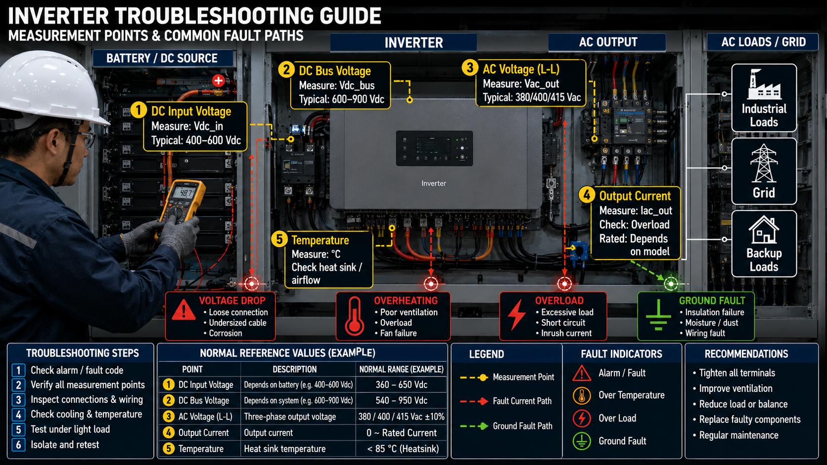
In field troubleshooting, the most valuable information is often lost after a reset. Record the fault code, DC-bus voltage, input/output voltage, current, temperature, operating frequency, load condition, and the exact moment of the trip before restarting the inverter.
1. Overcurrent — Check the Load Before the Inverter
An overcurrent trip commonly occurs during system startup, motor acceleration, or sudden changes in the connected load. These operating conditions can produce a temporary increase in current demand and may activate the inverter’s overcurrent protection mechanism.
Do not immediately replace the inverter. A systematic fault investigation should be performed first. Check the motor starting current, potential short-circuit conditions, mechanical jamming, incorrect motor parameter settings, and whether the connected cables are adequately sized for the required operating current.
Troubleshooting: Measure the phase current under actual operating conditions. Inspect the output wiring carefully for loose connections, abnormal resistance, or potential short-circuit conditions. Check the motor insulation condition to identify possible insulation degradation or leakage faults. Finally, compare the measured operating current with the inverter’s rated current to determine whether the system is operating within the specified capacity.
2. DC Bus Overvoltage — Look at Regenerative Energy
DC-bus overvoltage is frequently misunderstood as a conventional input-voltage problem. However, the actual cause may originate from the energy returned to the DC bus during dynamic operation.
With high-inertia loads, rapid deceleration can cause regenerative energy to flow back into the DC bus. If the braking circuit or energy-dissipation mechanism cannot effectively absorb this returned energy, the DC-bus voltage will continue to rise. Once the voltage exceeds the inverter’s defined protection threshold, the overvoltage protection mechanism is activated and the inverter trips.
Increasing the deceleration time can reduce the rate at which regenerative energy is returned to the DC bus. The brake resistor and braking chopper should also be inspected to ensure that the energy-dissipation circuit is operating correctly and within its specified capacity. In addition, changing the stopping strategy may help control the regenerative energy and prevent excessive DC-bus voltage rise.
3. DC Undervoltage — Measure Voltage at the Inverter Terminals
A battery or DC source may appear normal with no load but collapse during startup.
Measure the voltage directly at the inverter terminals while the load is operating. Do not rely solely on the voltage measured at the battery or power-supply output, as the actual terminal voltage may differ significantly under load conditions.
Loose terminals can introduce additional resistance and voltage drop. Long cable runs, corrosion, insufficient cable cross-section, and excessive source impedance can also contribute to substantial voltage drop, particularly under high-load conditions.
4. Overtemperature — Investigate the Thermal Path
If the inverter trips after 20–60 minutes rather than immediately, suspect thermal conditions.
Check ambient temperature, airflow, fan operation, heatsink contamination, cabinet ventilation, installation clearance, and continuous loading. A unit operating close to its rated power may also require thermal derating.
5. AC Grid Overvoltage or Undervoltage
Measure all phases at the inverter terminals during normal operation.
Do not rely on the nominal grid value. Long AC cables, weak grids, phase imbalance, loose terminals, or local voltage fluctuations can create trips that disappear when the system is idle.
6. Ground Fault or Insulation Failure
Ground-fault trips require particular attention because the inverter may be correctly protecting the system.
Inspect motor cables, PV strings, connectors, battery wiring, moisture ingress, and insulation resistance. In some installations, incorrect neutral-ground wiring can also trigger protection.
Never bypass ground-fault protection simply to keep the system running.
7. Overload — Separate Continuous Load from Startup Surge
A load may be acceptable during steady operation but exceed the inverter's short-term current capability during startup.
Motors, pumps, compressors and transformers can produce significant inrush current. Check both running power and starting demand.
8. Incorrect Parameters or Grid Settings
Many commissioning failures are configuration problems.
Verify rated voltage, frequency, motor parameters, acceleration/deceleration time, protection thresholds, battery limits, grid code, and control mode against the actual system.
A parameter that worked on a laboratory bench may be unsuitable after system integration.
9. Communication or Control Signal Failure
In PCS, ESS and industrial applications, a communication loss can cause the inverter to stop even when the power stage is healthy.
Check CAN/RS485 wiring, termination resistance, addressing, baud rate, grounding, shielding, connector quality, and controller timing. Also determine whether the inverter is receiving an external shutdown command.
10. Internal Hardware Fault — Only Diagnose This After External Causes
If voltage, current, temperature, wiring, grounding, load and parameters are all normal, then investigate the inverter itself.
Possible causes include damaged IGBT/MOSFETs, DC-link capacitors, relays, sensors, cooling fans, control boards, or gate-drive circuits.
The key principle is simple:
Do not replace the inverter until the external system has been eliminated as the cause.
A Practical Field Case
A 30 kW inverter repeatedly tripped on overcurrent during motor startup. The inverter passed the bench test, and the motor ran normally when started without mechanical load.
Instead of replacing the inverter, the engineering team measured the startup current and inspected the mechanical system. The actual problem was excessive mechanical resistance combined with an aggressive acceleration setting.
After correcting the mechanical issue and increasing the acceleration time, the inverter operated normally.
The lesson: a trip code identifies the protection event; the measurement identifies the root cause.
Field Troubleshooting Reference
Trip Symptom | First Check | Typical Root Cause | Recommended Action |
Overcurrent | Output current | Short circuit / surge | Check load & wiring |
DC Bus OV | DC-bus trend | Regeneration / surge | Extend deceleration |
DC Undervoltage | Voltage under load | Cable drop / weak source | Check terminals & cables |
Overtemperature | Heatsink temperature | Poor cooling / overload | Improve airflow |
AC OV/UV | Phase voltage | Grid fluctuation | Measure at terminals |
Ground Fault | Insulation | Cable / moisture | Insulation test |
Overload | Startup current | Inrush current | Check load capacity |
Communication | CAN/RS485 | Wiring / parameters | Check network |
Repeated Internal Fault | Fault history | Hardware | Service inspection |
This approach helps engineers evaluate voltage range, power level, isolation requirements, topology, thermal conditions and application constraints before hardware selection.
IDEALPLUSING Technical Support
For demanding applications such as ESS, industrial control and bidirectional power conversion, troubleshooting often begins with the system architecture rather than the converter itself.
Need a customized bidirectional isolated topology? Submit your electrical parameters to the IDEALPLUSING senior engineering team for a free technical evaluation.
Conclusion
An inverter trip should be treated as diagnostic information, not simply a product failure.
The most effective troubleshooting sequence is:
Record the fault → reproduce the condition → measure the electrical parameters → isolate the external system → verify settings → then inspect the inverter hardware.
This method reduces unnecessary component replacement and, more importantly, prevents the same fault from returning after commissioning.