Have you ever had a headache for the complex power management in electronic devices? Faced with different voltage requirements, the DC-DC converter is like an "electric magician" that can flexibly raise and lower the DC voltage to meet the working conditions of various circuits. However, its variety and different principles make people dazzled.
This article will explain 7 DC-DC converter circuits in the most popular language, so that you can easily master their working principles, typical applications and advantages and disadvantages.
What I share with you today is: DC-DC converters, mainly principles, classifications, circuit design, and actual circuit cases.
1. What is a DC-DC converter and its function?
A DC-DC converter is an electronic circuit that converts a DC voltage or current level to another DC voltage or current level. In most cases, the device uses only one power supply.
If different sub-circuits require different voltages to work properly, the input voltage needs to be converted to a lower or higher level, which can be done through a DC-DC converter.
In addition to converting voltage, DC-DC converters can be used to stabilize voltage without letting the voltage drop or rise too much. For example: One of the uses of automotive DC-DC converters is to regulate voltage fluctuations in automotive alternators.
2. Common DC-DC converters
2.1 Linear DC-DC converters
Linear converters reduce the output voltage through a resistive load, where a transistor is connected between the input and output. The input voltage is reduced by the voltage across the transistor, resulting in a drop in the output voltage.
The linear DC-DC converter is the simplest type of converter, where the voltage is reduced by a transistor placed between the input and output.
The circuit of the linear DC-DC converter is simple and cheap, but it also has many disadvantages. It can only be used to reduce voltage, and in addition, the efficiency decreases as the difference between the input and output voltage increases.
On the other hand, unused power is dissipated in the form of heat, and it is easy to overheat if the input and output voltages differ greatly.
Linear DC-DC is used for low-power devices and nodes that require high-quality output voltage and low output voltage ripple or for devices that are sensitive to electromagnetic interference.
Linear converters are often used in audio and video electronics, communication equipment, medical and measurement equipment.
2.2 Switching DC-DC Converter
Switching converters use switching elements to charge storage capacitors through electrical pulses. The voltage is then smoothed by the capacitors and transferred to the load. The output voltage level is defined by the duty cycle of the switching element.
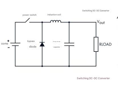
Switching DC-DC converters consist of a power switch, a conductor coil, a diode, and a storage capacitor. The number and arrangement of components affect the operation of the converter.
The input voltage is applied in pulses, but the capacitors smooth it. Compared with linear converters, switching converters have higher efficiency, which can reach 85-90%.
Because of the high efficiency, it does not generate much heat. It can be used to reduce and increase the output voltage, but it will generate more electromagnetic noise and require more components, which will be more expensive.
Practical application examples of DC converters:
Below is a real project that needs to power multiple sub-circuits in a device with multiple radio transmitters.
The sub-circuits require 5V, while the input voltage is 12V. The maximum current reaches 2A. In this case, it is not practical to use a linear converter because more than half of the energy will be dissipated as heat (full power up to 14W).
Installing a cooling heat sink is not a good option either, because the case is too small (10x10x1 cm). Instead, use the TPS54335 converter.
DC Converter Application Examples
When the difference between the input voltage and output voltage required by the subcircuit is too large, a switching converter can avoid generating too much heat.
2.3 Non-isolated and Isolated DC-DC Converters
Non-isolated DC-DC designs feature a direct connection between the input and output circuits (i.e., a single circuit), and can be used for low-power devices compared to isolated models. For example: communications, computers, automotive, and other industries.
Non-isolated and Isolated DC-DC Converters
Isolated converters, where the input and output are separated from each other, usually use a transformer that blocks the flow of DC between the two circuits.
Usually the primary and secondary are separated, and are widely used in high-voltage DC-DC converters. In addition, this design allows you to break ground loops, which can protect sensitive circuits from noise.
Can be used for power supplies for programmable logic controllers, industrial automation, and IGBT drivers.
Isolated Converter Circuit Example
For example, in the following example, an isolated converter must be used because the device operates in a humid environment. Here, the LM25017 fly-buck regulator is used.
Isolated Converter Circuit Example
The LM25017 fly-buck regulator is an ideal choice for systems where there is a risk of electric shock.
2.4 Step-down DC-DC Converter
A step-down converter produces a lower output voltage compared to the input.
In a simple step-down converter, the switching element (K) quickly turns the power on and off. The output voltage looks like a series of square waves. When the switch is open, the coil (L) and capacitor (C) accumulate energy.
The capacitor smoothes these waves into a DC voltage. When the voltage reaches the required level, the switching element turns off and the diode (D) turns on. The self-induced emf causes current to flow through the diode, and the energy accumulated in the coil charges the load.
Below is a simple step-down converter schematic.
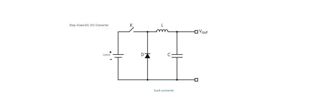
Buck converter
Buck converters are used in many areas, including battery chargers, multimedia players, game consoles, monitors, and televisions.
2.5 Boost DC-DC converter
Boost DC-DC can generate a voltage higher than the input voltage. In a typical boost converter, the induction coil receives almost all the current, and the closed diode does not allow the current to charge the capacitor and load.
Due to the higher current, the coil can accumulate more magnetic field energy compared to the buck schematic. When the voltage drops to a certain point, the power button turns off and the diode turns on.
The input voltage increases the energy stored in the coil, so that the output voltage of the boost DC-DC converter is higher than the input voltage.

Boost DC-DC converter
As shown above, the boost DC-DC converter has the same components as the buck converter, the switching element, the conductor coil, the diode, and the capacitor, but the arrangement is different.
Boost converters are commonly used in hybrid vehicles, lighting systems using energy-saving lamps, and portable lighting equipment.
2.6 Buck-bosst DC-DC Converter
A buck-bosst DC-DC converter can increase and decrease the input voltage to produce a higher or lower output level. It is often used when a wide input voltage range needs to be handled.
In this case, the converter uses 2 conductors and 2 capacitors to increase and decrease the voltage.
Buck-bosst DC-DC Converter
Buck-bosst DC-DC converters are often used in devices powered by lithium-ion batteries. Usually the converter steps down the voltage to the required level. However, as the battery voltage decreases over time, it will start to increase.
2.7 Inverting DC-DC Converter
The main function of an inverting DC-DC converter is to reverse the polarity of the output voltage. The output level can be higher or lower than the input level. When the device requires dual power supplies (such as operational amplifiers)
3. Basic Characteristics of DC-DC Converters
When choosing a DC-DC converter, you need to pay attention to the following characteristics and parameters. The most important ones are as follows:
3.1 Input Voltage
The input voltage is defined by the power supply used. Different power supplies provide different input voltages. When designing, you must ensure that the DC-DC converter can withstand these voltages.
3.2 Output Voltage
DC-DC converters can produce fixed or adjustable output voltages, ranging from a minimum to a maximum value. Generally speaking, the choice of model is determined by the voltage range required by the load.
3.3 Output Current
The output current defines the electrical power that the converter can provide.
3.4 Efficiency
The efficiency is the percentage of input power that is transferred to the output. It can be expressed as:
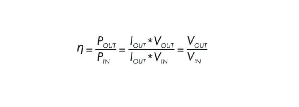
Efficiency
For example, the efficiency of DC-DC converters varies greatly. This parameter is crucial. For example, if the device is powered by a battery, the efficiency defines how long the device can operate before the battery must be replaced.
However, in some cases, efficiency is not so important. The energy lost in the conversion process is then dissipated as heat.
3.5 Temperature
Since the extra energy is converted into heat, overheating can become a serious problem. At this time, additional thermal protection must be used.
3.6 Size and Mounting
DC-DC converters are available in many package types. If they need to be mounted on a PCB, there are many mounting options, but size issues must also be considered.
4 Common Problems Related to DC-DC Converters
4.1 EMC Issues
Electromagnetic compatibility is the most obvious problem you may face when using a DC-DC converter. Switching DC-DC converters are very popular due to their high efficiency and generate electromagnetic noise. Therefore, such devices must be tested for electromagnetic compatibility to ensure that they do not cause electromagnetic interference to other devices.
Generally speaking, these problems can be solved by proper PCB layer stacking, additional capacitors and filter capacitors. For example, it is necessary to avoid installing the converter near sensitive components and subcircuits (especially conductor coils).
In the schematic below, you can see a ferrite bead (L2), as well as four ceramic capacitors (C5-8) and an electrochemical capacitor (C4). These components are installed there to protect the analog subcircuit from EM interference.
The ceramic capacitors suppress high-frequency noise from the converter, and the electrochemical capacitors smooth low-frequency fluctuations from different sources. This combination greatly improves the quality of the power supply.
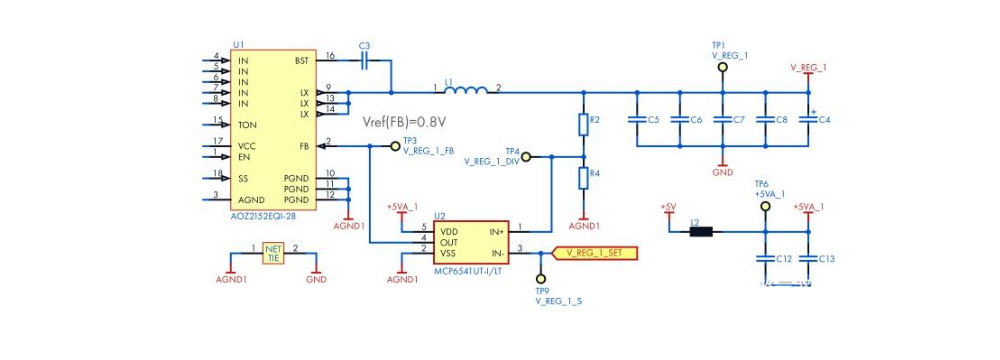
EMC Issues
See the four ceramic capacitors and one electrochemical capacitor in the upper right corner of the schematic.
4.2 Safety Issues
In many devices, the difference between input and output voltage can reach hundreds of volts, which can be very dangerous, so high voltage DC-DC converters must be used in devices.
1) Functional Insulation
Functional insulation between input and output circuits is only required for normal operation, but if the input to output insulation breaks down or fails, it will not provide adequate protection against electric shock. This protection level must meet at least one set of the standard's requirements:
Electrical clearance and creepage distance
Electrical strength test
Fault condition test
The DC-DC of the device is allowed to have functional insulation if the following conditions are met:
The AC-DC power supply uses reinforced insulation or double insulation between the AC input and DC output.
The AC-DC power supply uses basic insulation or supplementary insulation, and the secondary circuit of the DC-DC converter is connected to protective earth.
The AC-DC power supply has basic or supplementary insulation, and the primary circuit of the DC-DC converter is connected to protective earth.
2) Basic Insulation
This insulation level provides basic protection against electric shock. The device must meet all three groups (a, b, and c) requirements. This level is required if the AC-DC power supply has functional insulation between the AC input and DC output, and the secondary circuit of the DC-DC converter is connected to protective earth.
3) Supplementary Insulation
In addition to meeting the basic insulation requirements, this level adds an additional layer of protection, such as increasing the insulation penetration distance by 0.4 mm for peak voltages above 71V. This level of protection is required if the AC-DC power supply uses basic insulation between the AC input and DC output.
4) Double Insulation
This protection level combines basic insulation and supplementary insulation.
5) Reinforced Insulation
It is a single insulation system that provides the same level of protection as double insulation. It can contain multiple layers of protection, and reinforced insulation is required if the AC-DC power supply has no insulation or functional insulation between the AC input and DC output.
4.3 Thermal Considerations
DC-DC converters are mainly used in portable devices.
Most of the heat is generated by the transformer, so the thermal insulation system is rated according to the standard based on the interaction of its manufacturing materials at its high temperature. In most DC-DC converters, you can find a planar transformer built into the main PCB. Many engineers do not consider this a safety hazard unless the temperature exceeds the maximum rating of the PCB.
Overheating can be solved by a combination of methods. For example: In the figure below, you can see 4 power converters that generate a lot of heat. Using MOSFET transistors with lower static drain-source on-resistance means less energy is converted to heat.
In addition, wide parallel traces are made and many vias are added to allow heat to dissipate from both sides of the PCB.
DC-DC converter heat dissipation considerations
Pay attention to the trace width around the DC-DC converter on the PCB, which can help dissipate heat.
DC-DC converters are like "voltage transformers" in the electronic world. Whether it is buck, boost, or complex isolation, they silently provide accurate and stable energy for various devices. Through the explanation of this article, I believe you have a clear understanding of the 7 classic DC-DC topologies - from simple Buck/Boost to efficient bridge architecture, each circuit has its unique application scenario and design essence.
Share our interesting knowledge and stories on social media


