Introduction
In real power projects, “Isolated or Non-Isolated?” is not simply a topology selection question.
Many engineers initially focus on input voltage, output voltage, current, and efficiency. However, grounding, common-mode noise, EMI, fault current, and system safety often determine the correct topology.
A common misconception is that industrial, energy storage, or communication systems inherently require isolated DC/DC converters. However, this assumption is not universally applicable. If the system incorporates a clearly defined and appropriately designed grounding architecture, and if electrical isolation between the input and output is not an explicit functional or safety requirement, a non-isolated DC/DC converter can often provide a more straightforward solution. It can also offer greater system reliability, reduced design complexity, and improved cost-effectiveness.
1. The First Question Is Not “Which Converter?” — It Is “Do You Need Isolation?”
The first question in a real project should be:
“Does the system actually require galvanic isolation?”
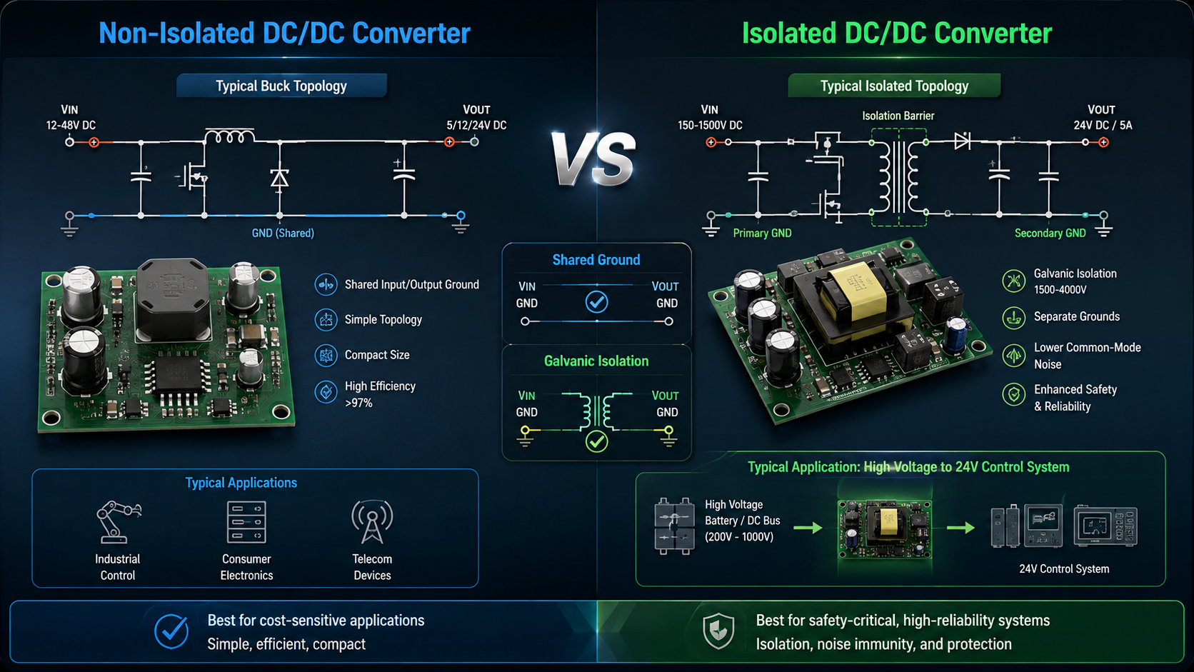
If the input and output can share a common ground and there is no personnel safety risk, different ground potential, or fault-isolation requirement, a non-isolated Buck or Boost Converter is usually a reasonable starting point.
Typical applications include 48 V to 24 V industrial control, 24 V to 12 V control systems, battery-powered loads, DC bus systems, and sensors or controllers.
By contrast, if the input and output must remain electrically isolated, such as when a high-voltage DC bus supplies a low-voltage control system, an isolated topology provides a clear system-level advantage.
2. Non-Isolated Converters: Higher Efficiency, Simpler Failure Modes
The main advantage of a non-isolated DC/DC converter is not simply lower cost. The entire power path is usually simpler.
Without a high-frequency transformer, the overall design eliminates one major magnetic component. This significantly simplifies the management of insulation requirements, parasitic parameters, and thermal considerations. Consequently, the converter structure can be more straightforward, while the associated design and engineering constraints are also reduced.
Typical benefits include a smaller PCB footprint. They also include a lower overall component count and reduced system cost. In addition, thermal management can be implemented more easily. The converter can achieve a fast transient response. System troubleshooting and maintenance are also simplified.
For example, in an industrial control system, the power conversion stage may be required to convert a 60 VDC input voltage to a regulated 24 VDC output voltage. The required output power may be approximately 120 W, depending on the specific operating conditions and system load requirements.
An isolated converter may initially appear attractive. However, if the system already uses a common DC negative reference and has no personnel safety requirement, a non-isolated Buck architecture can be more appropriate.
The result can be fewer components, smaller PCB area, lower losses, and simpler thermal management.
3. When Non-Isolated Designs Fail in the Field
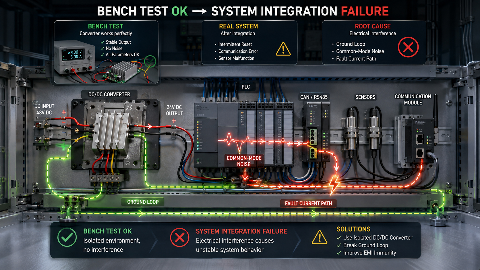
The biggest risk of a non-isolated design is often not conversion performance, but incorrect grounding architecture.
Typical field symptoms may include unstable communication after another device is connected to the system. Other symptoms may involve unexpected ADC noise or abnormal signal interference. In some cases, the converter may operate correctly during bench testing, yet fail to perform as expected after full system integration.
These problems are often associated with unintended current-return paths within the system. Such paths may form between power ground, signal ground, chassis ground, and communication ground, resulting in unwanted electrical interactions and potential system interference.
Therefore, engineers should analyze the entire grounding architecture rather than evaluating the DC/DC converter independently.
4. Isolated Converters: Pay for Isolation Only When It Solves a Real Problem
The main value of an isolated DC/DC converter is electrical isolation, fault separation, and improved control of complex grounding conditions.
Typical applications include high-voltage battery systems and energy storage systems. They also encompass EV power electronics, medical equipment, and industrial communication interfaces. In addition, isolated DC/DC converters are commonly applied to gate-driver power supplies and high-voltage DC bus systems, particularly where electrical isolation is required for safety, noise reduction, or system-level protection.
For example, in an energy storage system, the main battery may operate at several hundred volts DC while the controller or communication circuit requires only 12 V or 24 V.
In this case, isolation is not primarily about voltage conversion. It helps block dangerous potential differences, limit fault propagation, and reduce ground-loop risks.
5. Practical Trade-Off: Efficiency Is Not the Only KPI
Factor | Non-Isolated | Isolated |
Efficiency | Usually higher | Usually lower |
Cost | Lower | Higher |
PCB Size | Smaller | Larger |
Isolation | No | Yes |
Ground-loop control | Limited | Better |
Fault separation | Limited | Better |
EMI design | Simpler in some systems | More complex |
Thermal design | Easier | More challenging |
Typical use | Point-of-load, industrial control | HV systems, safety-critical interfaces |
Engineers should not treat “isolated” as automatically meaning “better.”
The real comparison should be system-level reliability and risk versus added cost and complexity.
6. A Better Engineering Decision Process
A practical decision process should follow this sequence:
Step 1 — Check safety requirements.
Determine whether high voltage, accessible conductors, or safety isolation requirements exist.
Step 2 — Check grounding architecture.
Determine whether input and output are allowed to share a common ground.
Step 3 — Check communication interfaces.
Evaluate whether CAN, RS485, Ethernet, or other interfaces introduce ground-loop risks.
Step 4 — Check fault propagation.
Determine whether a power-side fault can affect the control side.
Step 5 — Compare efficiency and thermal margin.
Do not evaluate only full-load efficiency. Check the actual operating range and worst-case ambient temperature.
Step 6 — Validate EMI at system level.
Do not rely only on tests performed on the standalone power board. The final integrated system is what matters.
7. Engineering Note: Don't Add Isolation to Fix the Wrong Problem
When an EMI test fails, some projects immediately consider changing to an isolated converter.
That is not always the correct solution.
If the real problem is the PCB return path, MOSFET switching loop, input filtering, or common-mode current path, adding isolation may only hide the problem instead of solving it.
On the other hand, if the system genuinely requires safety isolation, choosing a non-isolated topology only to improve efficiency can create much larger redesign costs later.
Topology should be selected at the system architecture stage, not after the prototype fails.
Need a Custom Isolated or Bidirectional Solution?
If a standard topology cannot meet your input range, output power, isolation voltage, efficiency, or bidirectional power-flow requirements, topology evaluation should begin early in the project.
Need a customized bidirectional isolated topology? Submit your electrical parameters to the IDEALPLUSING engineering team for a free evaluation.
Conclusion
There is no universally superior choice between isolated and non-isolated DC/DC converters. The optimal selection depends on the specific system requirements, operating conditions, and application constraints. Neither topology can be considered inherently superior in all applications or under all design conditions.
Non-isolated converters are generally well suited to applications where high conversion efficiency is a primary design objective. They are also advantageous when low cost, compact physical dimensions, and a relatively simple grounding architecture are among the key system-level priorities.
Isolated converters are more appropriate when high-voltage systems, safety isolation, fault separation, or complex grounding conditions are involved.
For engineers, the professional decision is not simply to select the product with the highest specifications. The correct topology should be determined by system grounding, safety, fault paths, EMI, thermal design, and total lifecycle cost.