Common topology modulation methods
If PWM control technology is applied to different power topologies, the modulation method of the control signal will be different.
Common modulation methods include: phase shift modulation, pulse frequency modulation, pulse width modulation, unipolar frequency multiplication modulation and bipolar modulation, etc. These modulation methods have mature packages in PPEC digital power control chips and can be directly applied, providing efficient, stable and reliable solutions for digital power research and development.
Next, we will introduce the modulation methods of some common power topologies:
Phase-shifted full-bridge topology:
Using phase-shift modulation, by adjusting the phase difference (i.e. phase shift angle) of the PWM signal of the bridge arm switching device, the duty cycle of the primary output voltage is changed to achieve the purpose of adjusting the output voltage.

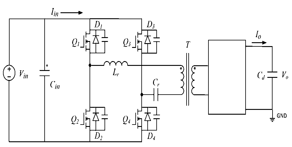
LC series resonant topology:
Using pulse frequency modulation, the output voltage is adjusted by controlling the frequency fs of the PWM signal. In practical applications, it often works in 0~0.5 times the resonant frequency fr mode and the switching frequency fs is higher than the resonant frequency fr mode.


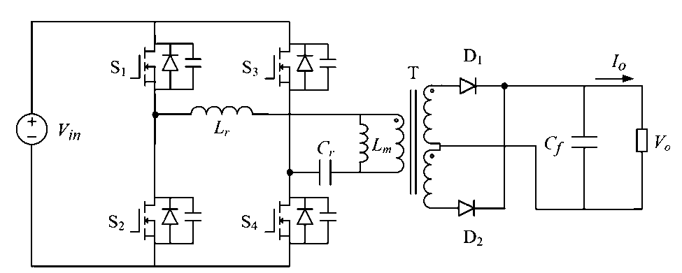
LLC resonant topology:
Pulse frequency modulation is often used to adjust the output voltage by controlling the frequency fs of the PWM signal. The converter often works in under-resonance mode, quasi-resonance mode and over-resonance mode.


Inverter/rectifier topology:
unipolar frequency modulation and bipolar modulation are often used. Unipolar frequency modulation uses two fundamental signals (ug, -ug) to intersect with the carrier signal to obtain two modulation signals, and the two signals interact to produce a unipolar frequency modulation signal. The bipolar modulation signal is generated by the intersection of a fundamental wave and the carrier, and its waveform is positive and negative within half a fundamental wave cycle.

Buck-boost topology:
pulse width modulation (PWM) and pulse frequency modulation (PFM) are often used. PWM uses a constant switching frequency and adjusts the pulse width (duty cycle) to achieve output voltage regulation. PFM adjusts the switching frequency to achieve output voltage regulation.
The basic control principles of PWM technology and common circuit applications are shared here. It should be noted that although PWM control technology simplifies the power conversion process and has the advantages of good stability, high efficiency and high reliability, the implementation of PWM technology has high requirements for switching devices and large circuit noise. Therefore, in the application, we must choose the appropriate control method according to actual needs.


