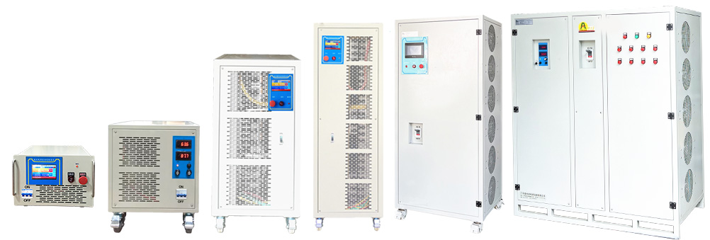
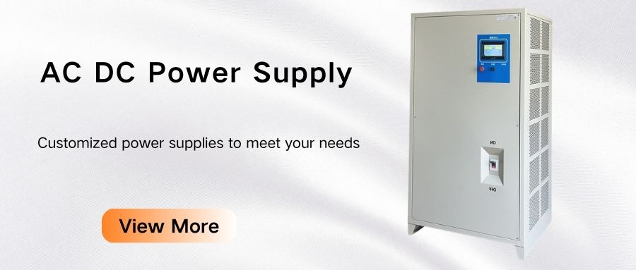
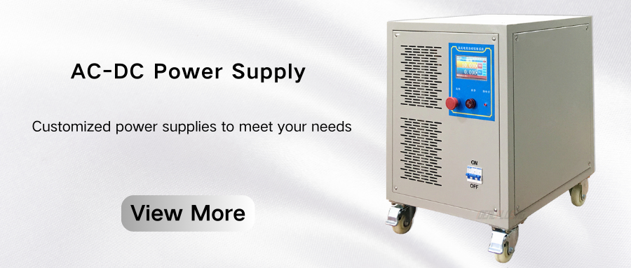
Electroplating power supply is actually a power converter that can convert the AC voltage of the power grid into low DC or pulse voltage, which is used for electroplating.
In the process of continuous development of science and technology, the content involved in the electroplating industry is increasing, and the scope of use is expanding. People's demand for plating is also increasing, requiring electroplating power supplies to have a higher operating frequency. Therefore, the research and development of new electroplating power supplies has attracted people's attention.
Modern power converters are gradually developing in the direction of high frequency, which has brought new opportunities for the development of electroplating power supplies.
Effectively increasing the switching frequency of switching devices has many benefits for power converters, such as increasing the density, volume and response capability of power converters.
The conversion technology of traditional electroplating power supplies limits the effective improvement of the working efficiency of power converters and cannot meet the trend of modern high frequency.

Research on the hardware design of high-power high-frequency switching electroplating power supply
Overall design plan
According to the design requirements, in order to effectively realize the high-power current output of the electroplating power supply, the power supply uses multiple sub-modules in parallel, in which the input end of the circuit is connected to the 380V three-phase AC power, and the current in the control circuits such as the CPU is provided through rectification and filtering. Part of it is transmitted to the sub-module power supply through the contactor and the main fuse, and rectified by the three-phase rectifier bridge to become a 540V DC voltage, which is provided to the full-bridge power conversion module through filtering, and then the DC voltage is filtered through rectification and filtering.
The CPU control unit and the LCD and keyboard are connected to each other to realize the adjustment, display, communication and protection of the voltage and current output.
Among them, the full-bridge phase-shifted zero-voltage switch is used as the main circuit of the high-frequency inverter circuit, and the soft switching technology is used to realize high-power and low-loss high-frequency inverter.
The high-frequency switch tube uses a high-power module, which can effectively improve the reliability of the power supply during use, and the high-frequency rectifier tube uses a Schottky rectifier module to effectively improve the power supply efficiency.
The main purpose of the control unit outputting the control signal is to achieve a rapid response of the main circuit output, so as to obtain dynamic and static output characteristics, and to achieve various input voltage fluctuations, and to achieve protection response for faults caused by various factors.
The main functions of the power supply system include: automatic voltage and current regulation according to the output voltage and current deviation; detection of the system output state through current and voltage meters; the system has overheat protection, overcurrent protection and water shortage protection, and also has a photoelectric three-dimensional alarm function; the voltage and current working modes can achieve the stability of the system operation.
The IGBT drive circuit is used, which is a voltage drive element, a fully controlled device, with a large input impedance, and is more sensitive to gate charge, with a threshold voltage of 3V-6V, so it has higher requirements for the drive circuit.
There are many IGBI drive circuits, and photoelectric coupling or transformer coupling is used in high-power occasions. The optocoupler driver is active on both sides, and the pulse width provided by it will not be limited. It can detect the collector voltage of the IGBT on-state, and can also realize short-circuit and overcurrent protection in various situations, and can also output overcurrent signals to the outside.
However, this method requires more working power supplies to be implemented, which increases the complexity of the circuit. On the contrary, the transformer-coupled driver does not need to set the working power supply, and has a faster working speed and higher input and output withstand voltage. Then this article uses transformer-coupled drive to obtain continuous reverse gate voltage during the shutdown process of the drive short circuit.
On the basis of using transformer-coupled drive, in order to enable the switch tube of the drive circuit to be turned on and off quickly, a high-speed driver chip is used in the design process, so as to provide a larger peak drive current.

High-frequency transformer
The high-frequency transformer is a magnetic component for energy transmission and electrical isolation. It is an important component in the switching power supply. Its performance directly affects the efficiency of the transformer itself and determines the performance of the power supply system.
The transformer design process includes the selection of three devices, namely the number of primary and secondary turns, the ratio of primary and secondary turns, and the magnetic core. In the process of selecting the magnetic core, the main thing is to choose the geometry and material. The main materials include ferrite and permalloy. Ferrite has ferromagnetism and high resistance, so it can be easily used in high-frequency transformers.
Output rectifier and RC absorption network
In the process of selecting the rectifier diode, the diode current should be fully considered. By calculating the rectifier diode current and rated voltage, sufficient amount should be reserved, and finally Schottky diode should be selected.
The main purpose of the PC absorption network is to prevent the output rectifier diode from reverse recovery during the shutdown process, which leads to ringing.
In the design process, the capacitance value can be selected as the parasitic capacitance value of the diode. The resistance value should be used to enable the capacitor to complete charging and discharging in one-tenth of the cycle, and close attention should be paid to whether the resistance power can meet the absorption requirements.
Through theoretical analysis, the design of the electroplating power supply was realized, and a water-cooled high-power high-frequency switching electroplating power supply with an operating frequency and power of 20kHz and 18kV was successfully developed. The main circuit experimental device in this article is a box structure with a small volume and light weight. The power components and the primary and secondary windings of the high-frequency transformer are all cooled by water. The three promotion tubes on the upper right are cooling water pipes, and the main circuit conductive path steel pipe is hollow.
Below the experimental device are the high-frequency transformer, filter circuit and output rectifier circuit. The working principle of electroplating is to pass the adsorbed oppositely charged ions of the power supply electrode, and the ion movement becomes current. However, due to the limitation of conditions, in order to realize the simulation of electroplating at the production site, sodium chloride solution is used as the electrolyte during the experiment, and the positive and negative electrodes of the electroplating power supply output and the aluminum plate are connected to each other and placed in the sodium chloride solution.
Shorten the distance between the plates, that is, increase the load and output current. Because there is current, the sodium chloride begins to react. The positive electrode of the power supply turns black due to the adsorption of negative ions, and the negative electrode of the power supply turns white. The larger the current, the more intense the reaction will be. The simulation system of the on-site fault can respond correctly, stop the pulse, protect the module, and switch between constant voltage and constant current, and the output voltage can be adjusted.
Application trend of plating power supply
High frequency and high efficiency
The switching power supply used by high-power and high-frequency switches can replace the traditional rectifier power supply, which can effectively reduce losses and increase power density.
Modern electroplating switching power supplies are mainly used in small and medium powers below 1500A, so the use of advanced power electronic devices and technologies can innovate the limitations of the output power of modern power devices and magnetic materials, and fully exert the power output capacity of the switch tube through the series and parallel connection of transformers, so as to effectively improve the output efficiency of the single-machine power.
Use multi-unit building block parallel technology to effectively improve the power output capacity. Soft switching technology can effectively reduce the switching loss of the device, thereby effectively increasing the switching frequency and optimizing the working environment of the device. This technology can reduce the power switch tube loss in the high-frequency state, improve the overall efficiency of the power supply, and effectively increase the working frequency of the power supply.
Intelligence
The electroplating process is required to eliminate the influence of human factors and reduce the process energy loss, which puts forward a higher demand for power supply intelligence. From the perspective of energy saving and improving process quality, in addition to the power supply device loss, process energy consumption also accounts for a large part of the electroplating process. The main factors affecting process energy consumption are current efficiency and tank pressure. By detecting parameters such as electrolyte temperature and concentration, the power supply current and voltage output can be reasonably adjusted to achieve energy saving and efficiency improvement and improve process quality.
From the perspective of control, the electroplating process converts electroplating energy into a nonlinear time-varying system, and it is impossible to create a standard model for control.
Intelligent control can be independent of people, and can be controlled accordingly through people's operating knowledge and experience, thereby effectively improving the process quality and performance of electroplating power supply.
Therefore, in the continuous development of electroplating technology, it is necessary to develop intelligent power supply equipment that meets the needs of different processes, so as to meet the development needs of new technologies in modern society.


