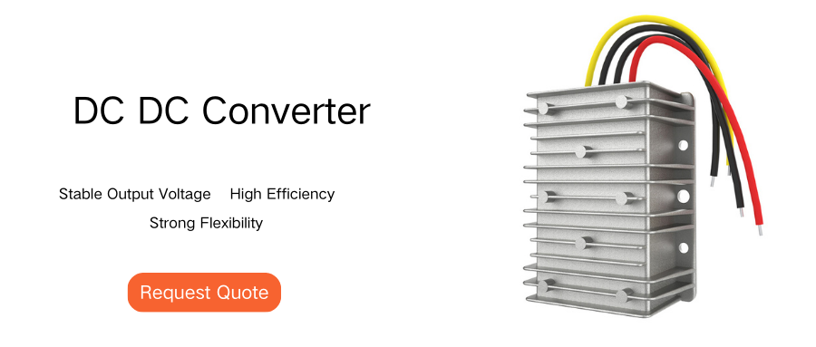
In power electronics, a DC/DC buck converter is a common power converter widely used in various electronic devices. The following will introduce its design principles and examples in detail.
Basic principles of DC/DC buck converter
1. Working principle
The DC/DC buck converter uses switching elements (such as MOSFET) and energy storage elements (such as inductors and capacitors) to reduce voltage. Its basic working principle is as follows:
Conduction phase: the switching element is closed, the input voltage supplies power to the load through the inductor, and the inductor stores energy.
Turn-off phase: the switching element is disconnected, the inductor releases energy, and continues to supply power to the load.
2. Main components
Switching element: MOSFET is usually used.
Energy storage element: inductor (L) and capacitor (C).
Diode: used to provide a freewheeling path when the switch is disconnected.

Design steps and examples
1. Determine the design parameters
Suppose we need to design a buck converter with an input voltage of 12V, an output voltage of 5V, and an output current of 1A.
Input voltage (Vin): 12V
Output voltage (Vout): 5V
Output current (Iout): 1A
Switching frequency (f): 100kHz
2. Select inductor (L)
The selection of inductor needs to consider current ripple and energy storage requirements
3. Select capacitor (C)
The selection of capacitor needs to consider the ripple of output voltage,
Simulation and verification
Use simulation software (such as LTspice) to verify the design to ensure that the circuit works stably under different load and input voltage conditions.
Practical application precautions
Thermal management: Ensure good heat dissipation of switching elements and inductors.
EMI suppression: Reasonably layout the circuit to reduce electromagnetic interference.
Protection circuit: Add overcurrent and overvoltage protection functions.
Conclusion
The above is a detailed explanation. I hope you like it. If you have any questions, please contact us and leave a message for discussion!


