The current situation and development trend of communication power supply
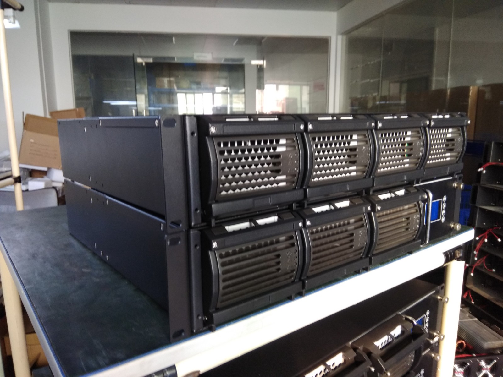
Communication power supply is often called the "heart" of communication equipment. It has an incomparable important position in the communication bureau (station). With the continuous development of related disciplines and technologies, communication power supply is also developing and progressing, mainly manifested in the development of power supply mode from centralized power supply to decentralized power supply, the application of new power electronics technology in rectifiers, the application of valve-controlled sealed lead-acid batteries and centralized power supply networking monitoring.

Power supply mode develops towards decentralized power supply
Not long ago, some users in China still adopted centralized power supply mode, that is, power supply equipment was installed in the power room and battery room, and the centralized power supply supplied power to various communication equipment.
This power supply mode is produced under the conditions of using thyristor phase-controlled rectifiers and ordinary lead-acid batteries. Because the above equipment is large and bulky, noisy, and has acid mist to pollute the environment, all power supply equipment can only be installed in the power room and battery room on the ground floor of the building. The centralized power supply equipment is far away from the communication load center, the DC transmission loss is large, the installation and operation costs are high, and the system reliability is poor.
Since the 1980s, the emergence and increasing application of switch rectifiers and valve-controlled lead-acid batteries (i.e., maintenance-free batteries) have made distributed power supply possible. In the distributed power supply mode, the AC power system can still adopt the centralized power supply mode, but the power supply equipment (rectifier, battery, AC/DC distribution panel) is moved to the communication room, and there are many ways to divide it according to the specific situation of the communication system.
Compared with the traditional centralized power supply method, it has the advantages of less comprehensive investment, convenient expansion, more reliable operation, easy to realize intelligent management and unattended operation. Of course, distributed power supply also has certain defects: the number and cost of batteries required are increased, and there are higher requirements for the reliability of AC power supply, electromagnetic compatibility, performance of power supply equipment, and technical level of maintenance personnel.
The requirements of the distributed power supply mode for high-frequency switch rectifiers are as follows: small size, light weight, high efficiency; strict requirements for electromagnetic compatibility (EMC) indicators; wide AC input voltage range; attention to appearance structure; and perfect management functions for battery packs.
The requirements of the distributed power supply mode for batteries are as follows: small size, light weight, high power density; reliable sealing; high tensile strength of the battery tank shell, no deterioration of the safety exhaust valve; good charging and discharging characteristics, etc.

Application of new power electronics technology in rectifiers
The rectifier is the part of the entire communication power supply system that has the greatest impact on system reliability, the highest technical content, and the fastest technical update. In the early days, thyristor (silicon-controlled thyristor) phase-controlled rectifiers were mostly used, and now they have been gradually replaced by high-frequency switching rectifiers. With the rapid development of power electronics technology, the technology and products of high-frequency switching rectifiers are also rapidly updated. At present, the development direction of power electronics technology and high-frequency switching rectifiers is: high power density (high frequency), high reliability; high efficiency, low electromagnetic interference (EMI).
The switching device is the core device of the switching rectifier. The switching device used in the early rectifier is the thyristor (SCR), which controls the output voltage by changing the conduction angle. The operating frequency is the industrial frequency (50Hz), which seriously pollutes the power grid. In addition, the operating frequency of the inductor and capacitor of the corresponding rectifier is also the industrial frequency, resulting in a large and bulky volume and low power density.
Now, new generation switching devices such as MOSFET and IGBT are mostly used. The former can work at a frequency of several hundred kilohertz or even megahertz, and the latter can also reach hundreds of kilohertz after using soft switching technology. It lays the foundation for the high frequency and high power density of rectifiers.

Development of soft switching technology
The main component of the switching power supply is the DC-DC converter. DC-DC power conversion technology has always been the focus of power electronics discipline and industry research. DC-DC conversion technology has undergone a process from hard to soft.
In the 1960s, a time ratio control (TRC) power change technology was applied, including PWM and PFM. Its advantage is simple control, and its disadvantage is the use of hard switching technology. The so-called "hard switching" means that the power device works with greater electrical and thermal stress. There are two main problems with hard switching: one is that the switching loss is large, and the loss is proportional to its switching frequency; the other is that due to factors such as energy storage elements (including distributed inductance and capacitance) and non-ideal characteristics of switching devices, its working area may exceed the safe working area of the switch tube. These two problems work together to reduce the reliability of the converter.
In order to enable the switching power supply to operate efficiently at high frequencies, in the early 1980s, Professor Li Zeyuan of VPEC in the United States and others proposed the concept of soft switching. The essence of the so-called "soft switching" is to add an LC resonant circuit to the hard switch. When the switch changes, the LC resonance is forced to quickly change the current or voltage on the switch to zero, thereby turning the switch into a zero voltage switch (ZVS) or a zero current switch (ZCS).
The ideal value of the turn-on and turn-off loss of the soft switch is zero. The switching frequency can be increased to the megahertz level, and the volume and weight of the switching power supply are further significantly reduced.

The application of soft switching technology has gone through three stages so far.
The first is the resonant mode. It uses the principle of resonance to make the current or voltage in the switching device change according to the sine law. When the current or voltage naturally passes through zero, the device is turned off or turned on.
The second is the quasi-resonant mode (QRC). The quasi-resonant switch is to add a resonant network to the PWM switch and use local resonance to achieve ZVS or ZCS. The characteristics of the resonance and quasi-resonant modes are to soften the switch, reduce the electrical and thermal stress of the device, and make high frequency possible.
However, there is a disadvantage that variable frequency control is required, so the control method is not as convenient as PWM control; and magnetic components such as transformer inductance are designed according to the lowest frequency, which makes it difficult to achieve miniaturization; in addition, due to frequency changes, transformers and inductors are difficult to optimize and design, and the working state is not ideal.
Since the late 1980s, soft switching technology has entered the third stage, which is to combine PWM technology with quasi-resonant technology, so that the converter works as a ZCS or ZVS quasi-resonant converter for part of the time in one cycle, and works as a PWM converter for the other part of the time. In this way, the converter has both the soft switching characteristics of voltage zero crossing or current zero crossing control and the characteristics of PWM constant frequency width modulation.
At present, there are two main types of soft switching methods: zero switching-PWM conversion and zero conversion-PWM conversion. Both technologies are hot topics of research and represent one of the highest technologies of power conversion to a certain extent. Zero conversion-PWM converters are currently mostly in the laboratory stage, while zero switching-PWM conversion has been widely used in many power supply manufacturers around the world.
Research on soft switching technology is being carried out in the power electronics industry, and corresponding circuit topologies and soft switching control implementation methods are emerging in an endless stream.


