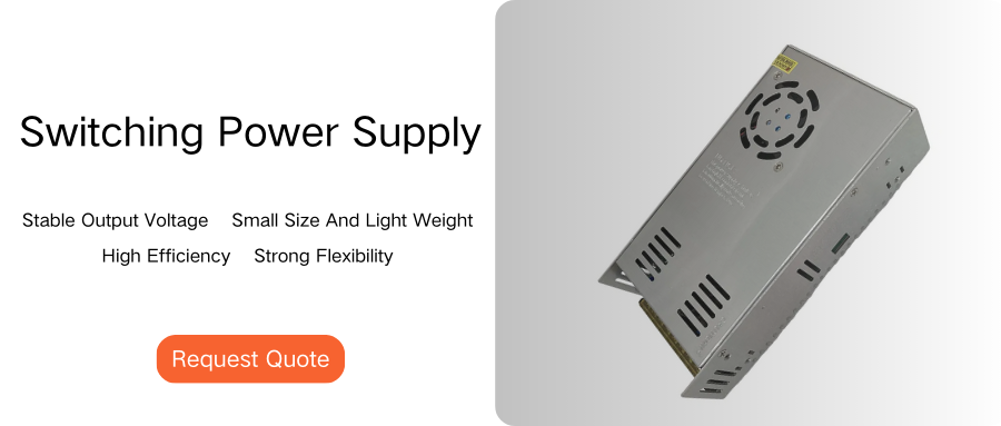
Switching power supply (SMPS), also known as switching power supply or switching converter, is a high-frequency power conversion device and a type of power supply. Its function is to convert a certain level of voltage into the voltage or current required by the user through different forms of architecture. The function of ordinary power supply is to convert the input AC mains (AC110V/220V) into several low-voltage DC power supplies required by hardware through an isolation switch step-down circuit: 3.3V, 5V, 12V, -12V, and provide a computer with 5V standby (5VSB) shutdown function in standby state. Therefore, the power supply is equipped with both high-voltage and high-power components.
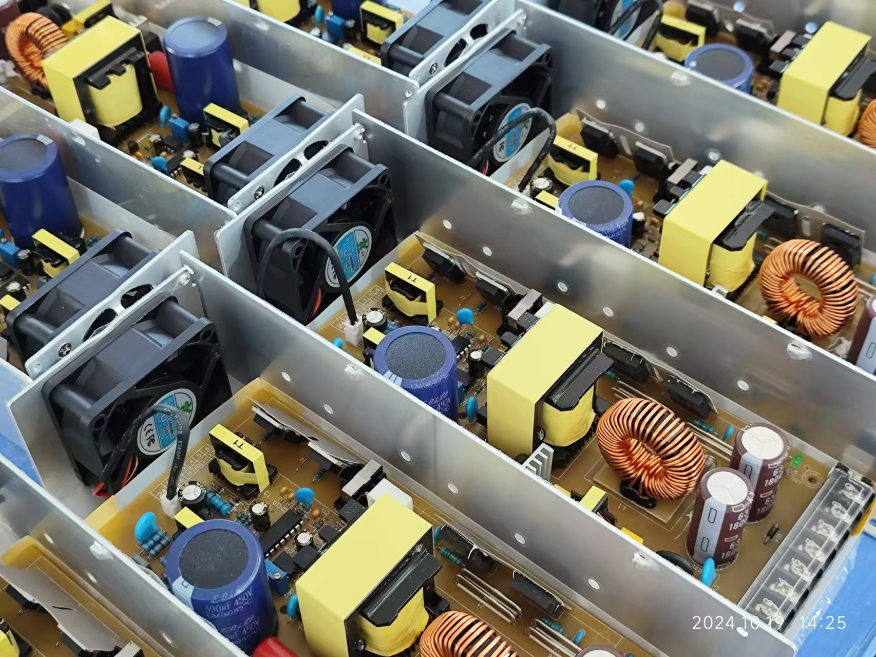
The power conversion process is AC input → EMI filter circuit → rectifier circuit → power factor correction circuit (active or passive PFC) → power stage primary side (high voltage side) switching circuit converted into pulse current → main transformer → power stage secondary side (low voltage side) rectifier circuit → voltage adjustment circuit (such as magnetic amplifier circuit or DC-DC conversion circuit) → filter (smooth output ripple, composed of inductor and capacitor) circuit → power management circuit that monitors output.
The following introduces the common components of the EMI filter circuit at the AC input end:
AC input socket
The external AC power input is checked here for the first time. First, add a second-order EMI at the AC input end to block interference from the power line to prevent the switching noise generated when the power supply is working from propagating through the power line and interfering with other electrical devices. (EMI) (Electromagnetic Interference) (EMI) (Electromagnetic Interference) ( The purpose of the low-pass filter (filter) is to bypass or direct the high-frequency noise contained in the AC power to the ground line, allowing only the waveform of about 60Hz to pass.
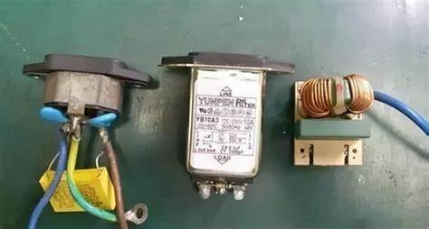
X capacitor (Cx, also known as cross-line filter capacitor)
The goal of this EMI filter circuit is to reduce the low normal noise of the power line by bridging the capacitor between the live wire (L) and the neutral wire (N).
![]()
Y capacitor (Cy, also known as line bypass capacitor)
To minimize high normal mode and common mode noise, the Y capacitor is connected between the floating ground (FG) and the live wire (L)/neutral wire (N).
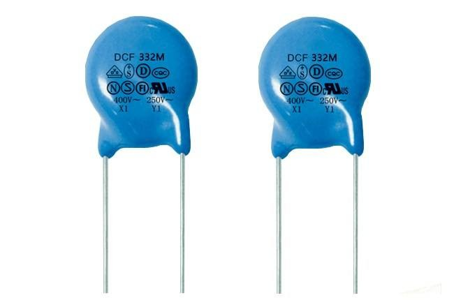
FG point in the computer power supply It is connected to the metal casing, ground wire (E), and output terminal 0V/GND in the figure, so when the ground wire is not connected, it will be connected through two series connections-connected wires. When the human body touches the Cy capacitor, it divides the potential difference of half the input power supply (Vin/2), and may induce inductance.
Common mode choke coil (cross-link inductor)
In order to eliminate the low-pass common mode and RF noise of the power line, the common mode choke coil is connected in series with the live wire (L) and the neutral wire (N) in the filter circuit. The input line of some power supplies adopts a design of surrounding the magnetic core, which can be regarded as a basic common mode choke. It has a ring and square shape, similar to a transformer, and some exposed coils can be seen.
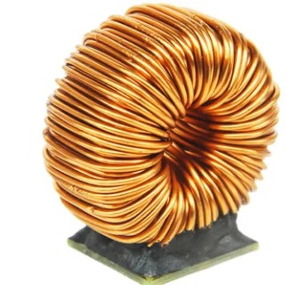
The noise between the L/N line and the ground wire E is called common mode noise, while the noise between the L and N lines is called normal mode noise. The fundamental purpose of the EMI filter is to eliminate and block these two types of noise. After the EMI filter circuit is the transient protection circuit and the rectifier circuit, common components As follows.
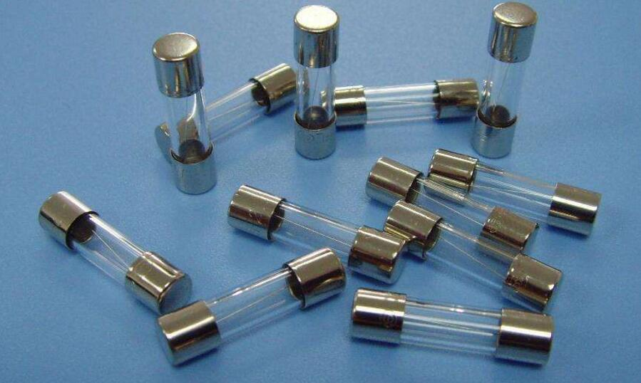
Fuse
When the current flowing through the fuse exceeds the rated limit, the fuse will melt and protect the connection with the back-end circuit. The fuse used in the power supply is usually a fast-acting type, but it is best to be an explosion-proof type. The main difference between this fuse and the standard fuse is that the outer tube is a beige ceramic tube with a fireproof material inside to prevent sparks when it melts.
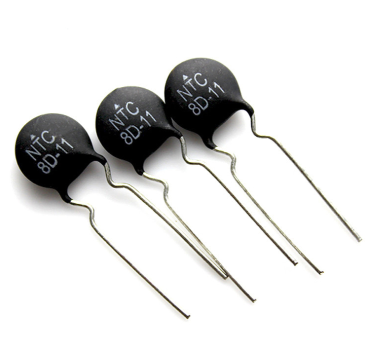
Negative Temperature Coefficient Resistor (NTC)
When the power is turned on, the electrolytic capacitor at the high-voltage end of the power supply is in a non-charged state. Excessive current surges and line voltage drops will occur during the charging process, which may cause the bridge rectifier and other components to exceed their rated current and burn out. When the NTC When connected in series with the L or N line, its internal resistance can limit the current when charging, and the negative temperature coefficient means that its resistance value decreases as the temperature rises, so when the current flows through the body, the resistance decreases. In order to reduce unnecessary power consumption, the resistance value will gradually decrease as the temperature rises.
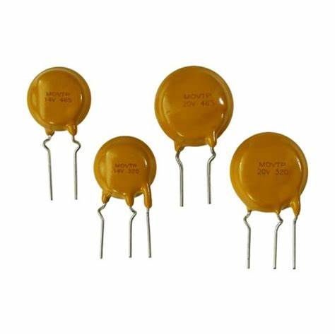
Metal Oxygen Varistor (MOV)
On the back of the fuse, the varistor is connected between the live wire and the ground wire. When the voltage difference between the two ends is less than its rated voltage value, the body presents a high impedance; when the voltage difference exceeds its rated voltage value, the body resistance drops rapidly. It is estimated that there is a short circuit between LN and the front-end fuse. Due to the current generated by the short circuit, the front-end fuse will melt to protect the back-end circuit. When the body is subjected to excessive power, it will occasionally self-destruct to remind the user that there is a problem with the device.
Bridge Rectifier
There are four diodes connected alternately in the internal bridge rectifier. Its job is to perform full-wave rectification on the input AC power for use by the back-end switching circuit.
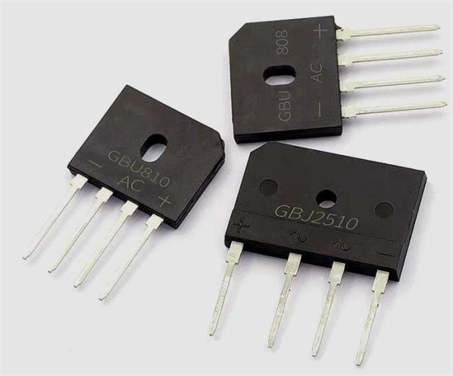
Its appearance and size will vary depending on the rated voltage and current of the component. Some power supplies will install it on a heat sink to help dissipate heat and ensure long-term stability. After rectification, it enters the primary switching circuit of the power stage. The components in this section define the maximum output capacity of each channel of the power supply and are key components.


