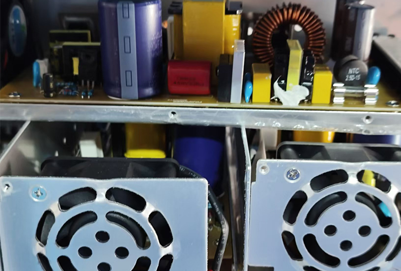
Switching power supplies do not require heavy power transformers, and have the advantages of small size, light weight, and high efficiency. In addition, there are finished switching power supply integrated control modules on the market, which greatly simplifies power supply design and debugging.
Therefore, they are widely used in most electronic devices (such as computers, televisions, and various control systems). However, the various noises generated by the switching power supply itself form a strong source of electromagnetic interference.
These interferences are significantly enhanced with the increase of switching frequency and output power, posing a potential threat to the normal operation of electronic equipment.
There are many types of Switched-mode power supply, the most common ones are:

1.According to the circuit structure of the converter, it can be divided into series-parallel type and DC conversion type
2. According to the excitation method, it can be divided into self-excitation and other excitation
3.According to the combination of switch tubes, it can be divided into bridge type, half-bridge type, and push-pull type
But no matter what type of switching power supply, it uses the opening and closing of semiconductor devices to work, and controls the output voltage by the opening and closing time ratio.
Since it usually works at a switching frequency of more than 20kHz, the dv/dt and di/dt in the power supply line are very large, generating large surge voltage, surge current and other various noises. They are conducted outward in common mode or differential mode through the power line, and also radiate noise to the surrounding space.
The following takes this as an example to analyze the main reasons for the noise generation
Noise of the switching circuit
Electromagnetic radiation: When the power supply is working, the switch tube T is in a high-frequency on-off state. In the high-frequency current loop composed of the primary coil L of the pulse transformer, the switch tube T and the filter C, a large spatial radiation noise may be generated.
If the filtering of C is insufficient, the high-frequency current will also be conducted to the AC power supply in a differential mode.
The second is the surge voltage caused by the inductive load. In the switching circuit, the load of the switch tube T is the primary coil L of the pulse transformer, which is an inductive load.
Therefore, when the switch tube is turned on and off, a high surge voltage appears at the * of the primary coil of the pulse transformer, which is likely to cause damage to the electronic devices in the same circuit (especially the switch tube T).
Noise of the secondary rectifier circuit
The first is electromagnetic radiation. When the power supply is working, the rectifier diode D is also in a high-frequency on-off state. The high-frequency switching current loop is composed of the secondary coil L of the pulse transformer, the rectifier diode D and the filter capacitor C, which may radiate noise to the space.
If the capacitor C is not filtered enough, the high-frequency current will be mixed with the output DC voltage in the form of differential mode, affecting the normal operation of the load circuit.
The second is surge current. When the silicon diode is forward-conducted, the charge in the PN junction is accumulated. When the diode is reversely voltageed, the accumulated charge will disappear and generate reverse current.
Since the frequency of D in the secondary rectifier circuit is very high during the switch conversion, that is, the time from conduction to cutoff is very short, the stored charge will disappear in a short time, which will generate a surge of reverse current.
Due to the existence of distributed capacitance and distributed inductance in the DC output line, the interference caused by surge becomes a high-frequency attenuated oscillation.
Noise of the control circuit
The pulse control signal in the control circuit is the main source of noise.
The noise caused by distributed capacitance, the role of Ci; although there is an insulating gasket between the heat sink K and the collector of the switch tube T, due to its large contact surface and thin insulating gasket, the distributed capacitance Ci between the two cannot be ignored at high frequencies.
Therefore, the high-frequency current will flow to the heat sink through Ci, then to the chassis ground, and finally to the protective ground wire PE of the AC power supply connected to the chassis ground to generate common-mode radiation.
The second is the role of Cd. The distributed capacitance Cd between the primary and secondary of the pulse transformer may directly couple the high-frequency voltage on the primary side to the secondary side, generating common-mode noise of the same phase on the two power lines used as DC output on the secondary side.


