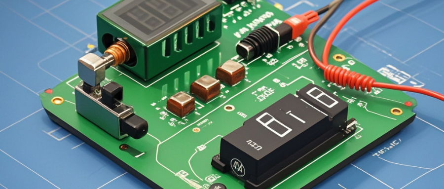
Making your own constant current constant voltage adjustable power supply is a relatively complex task that requires some basic knowledge of electronics and related circuit design skills. The following is a step-by-step guide to help you make your own constant current constant voltage adjustable power supply.

Part I: Theoretical Basics
Understand the principles and application areas of constant-current constant-voltage power supplies. A constant-current constant-voltage power supply is a type of power supply that is capable of providing a constant current and voltage output under a given load. This type of power supply is commonly used in electronics labs, homemade circuit boards, and other applications where a constant current and voltage output is required.
Understand basic electronic components and circuit fundamentals. Before making your own constant current and constant voltage adjustable power supply, you need to understand the characteristics and working principles of basic components such as capacitors, inductors, diodes, transistors, and operating amplifiers. In addition, you need to understand some common circuit topologies, such as voltage regulator circuits and current source circuits.
Part II: Designing Power Supply Circuits
Select a topology suitable for designing a power supply circuit. Common constant-current constant-voltage power supply topologies include charge pumps, buck linear regulators, boost linear regulators, switching regulators, and so on. Select the appropriate topology based on your application requirements and design constraints.

Calculate the parameters of the power supply circuit based on the design requirements. Calculate the required component parameters, such as capacitor tolerance, inductor value, resistor value, etc., based on current and voltage requirements. Common parameter calculation methods include calculating overload protection resistors based on output current and voltage, calculating capacitor tolerance values for voltage regulator circuits, and so on.
Draw the schematic diagram of the power supply circuit. According to the selected topology and calculated parameter values, use electronic design software or manually draw the schematic diagram of the power supply circuit. Ensure that the schematic is correct and clear.
Select and source components required for power supply circuits. Select appropriate components such as capacitors, inductors, diodes, transistors, and operational amplifiers based on the schematic diagram and parameter requirements of the power supply circuit. Pay attention to the quality and reliability of the components when purchasing.
Part III: Making the Power Supply Circuit
Prepare the tools and equipment needed for circuit fabrication. This includes soldering tools, multimeters, oscilloscopes, etc. Make sure the tools and equipment are working properly.
Transfer the circuit schematic to the circuit board. Different methods can be used, such as traditional etching techniques, tin spraying techniques, etc. Choose the appropriate method according to your proficiency and the actual situation.
Soldering the circuit board. According to the connection points on the circuit board and the pins of the components, use soldering tools to solder the components to the circuit board. Ensure the quality of soldering to avoid problems such as short circuits and false soldering.
Connect the parts in the power supply circuit. Use wires to connect the components and connection points according to the circuit schematic. Take care to keep the circuit neat and compact.
Check the connections and soldering of the power supply circuit. Using a tool such as a multimeter, check that the soldering on the circuit board is correct and that the connections are stable. Repair and adjust as necessary.
Part IV: Testing and Debugging the Power Supply Circuit
Perform initial testing. Connect the fabricated power supply circuit to the power supply and load and perform initial tests. Check that the current and voltage outputs meet the design requirements.
Perform performance tests. Using a load simulator or other suitable load measurement tool, perform performance tests of the power supply circuit. This includes measuring metrics such as current and voltage stability, ripple, and noise.
Adjust and improve the power supply circuit. Based on the performance test results, adjust the component parameters and connections in the power supply circuit for optimization and improvement. Multiple debugging and improvement may be required to achieve the desired performance.
Summarize the process of designing and building a homemade constant-current, constant-voltage adjustable power supply. Record details and lessons learned at each step for future reference and improvement.
Perform optimization of the power supply circuit. Optimize the power supply circuit based on actual application requirements and performance evaluation results. Optimization of component selection, circuit layout, and power supply method may be required.

Conduct safety and reliability tests. Ensure that the power supply circuit meets the safety and reliability requirements. Common tests include overload protection tests, short circuit protection tests, temperature tests, etc.Prepare detailed reports and documentation. Record the design, fabrication and testing process of the power supply circuit in detail and prepare reports and documents. Including schematic diagrams, parameter calculation results, fabrication steps, test results and so on.
I hope the above can help you accomplish the task of making your own constant current constant voltage adjustable power supply. As you delve into your research and practice, please ensure safety and signal performance, and follow relevant guidelines and standards.


