We all know that power sources come in two types: alternating current (AC) and direct current (DC). However, in many cases, conversion between these power sources is necessary.
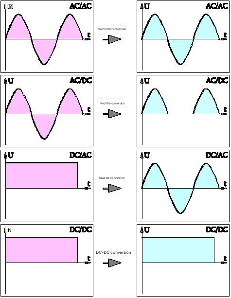
1. Converting AC to AC Using a Transformer
Transformers can both step down and step up voltages, and can even be used for isolation without changing the voltage.
A transformer is a device that uses the principle of electromagnetic induction to change AC voltage. Its main components are a primary coil, a secondary coil, and an iron core (magnetic core). Its main functions include voltage conversion, current conversion, impedance conversion, isolation, and voltage stabilization (magnetic saturation transformer).
Transformers can be categorized by their use: distribution transformers, power transformers, fully sealed transformers, combined transformers, dry-type transformers, oil-immersed transformers, single-phase transformers, furnace transformers, rectifier transformers, reactors, anti-interference transformers, lightning protection transformers, box-type transformer test transformers, angle transformers, high-current transformers, and excitation transformers. Transformers are essential equipment for power transmission and distribution and are widely used in industry, agriculture, transportation, urban communities, and other fields.
Principle
A transformer is a device that uses the principle of electromagnetic induction to change AC voltage. Its main components are a primary coil, a secondary coil, and an iron core (magnetic core). In electrical equipment and wireless circuits, it is often used for voltage stepping, impedance matching, and safety isolation. In a generator, whether the coil moves through a magnetic field or the magnetic field moves through a fixed coil, an electric potential is induced in the coil. In both cases, the value of the magnetic flux remains constant, but the amount of magnetic flux intersecting the coil changes. This is the principle of mutual induction. A transformer is a device that uses electromagnetic mutual induction to convert voltage, current, and impedance.

2. Converting AC to DC is called a rectifier
Common examples are rectifier diodes and thyristors. Almost all household appliances and computers have rectifiers installed in their power supplies.
A rectifier is a device that converts AC to DC and is used for powering devices and detecting radio signals. Rectifiers can be made from vacuum tubes, igniter tubes, solid-state silicon semiconductor diodes, mercury arc diodes, and other materials. Conversely, a device that converts DC to AC is called an inverter.
In a standby UPS, only the battery is charged and no load is supplied, so only the charger is required. In a double-conversion UPS, this device both powers the inverter and charges the battery, hence the name rectifier/charger.
A rectifier is a rectifying device—simply put, it converts alternating current (AC) into direct current (DC). It has two main functions: first, it converts AC into direct current (DC) and filters it before supplying it to the load or inverter; second, it provides charging voltage for the battery. Therefore, it also acts as a charger.
Principle
The AC power generated by a car's alternator is converted to DC by a rectifier, but its waveform still exhibits irregular fluctuations, directly affecting the accuracy of the vehicle's ignition. The output voltage cannot be maintained relatively constant, resulting in varying energy levels at each spark plug ignition. This can easily cause engine jerking, resulting in jerky shifts, slow and weak acceleration, unstable idling, and inefficient air conditioning. This significantly reduces the performance and service life of onboard electrical equipment. Coupled with the aging of older vehicles' circuit systems and the increased resistance of circuits, the impact on vehicles becomes increasingly significant. Electronic rectifiers help eliminate noise interference, stabilize output voltage, improve the power system's transient discharge capability, increase torque output, speed up throttle response, extend battery life, shorten engine start-up time, and improve ignition efficiency. These benefits are particularly pronounced in smaller vehicles.
A semiconductor PN junction conducts a large current when forward biased and a small current when reverse biased. A rectifier diode utilizes this unidirectional conductivity to convert AC current into DC. Devices with a current capacity below 1A are generally called rectifier diodes, while those with a current capacity above 1A are called rectifiers. Commonly used semiconductor rectifiers include silicon rectifiers and selenium rectifiers, available in a wide range of specifications, with voltages ranging from tens of volts to several kilovolts and currents from a few amperes to several thousand amperes. Rectifiers are widely used in various types of rectified power supplies. High-power rectifier power supplies require rectifiers with high current capacity, high breakdown voltage, and excellent heat dissipation. However, these devices have large junction areas and high junction capacitance, resulting in very low operating frequencies, generally below tens of kilohertz. Silicon, with its wide bandgap and excellent thermal conductivity, is suitable for high-power rectifiers. High-voltage silicon stacks are often used in high-voltage rectifiers. These stacks consist of multiple rectifier die connected in series. Their reverse withstand voltage is determined by the die's withstand voltage and the number of dies in series, and can reach hundreds of kilovolts. If a high-frequency rectifier circuit is used at very high frequencies, when the AC voltage cycle is comparable to the rectifier's recovery time from on to off, the rectifier will no longer rectify the high-frequency voltage. To accommodate high-frequency operation, gold doping is often used in silicon rectifiers to shorten the lifetime of injected minority carriers, thereby reducing recovery time.
To reduce the possibility of device damage due to overvoltage breakdown and improve the reliability of the rectifier, silicon avalanche rectifiers can be used. In this device, when the reverse voltage exceeds the allowable peak, uniform avalanche breakdown occurs across the entire PN junction, enabling the device to operate at high voltage and current, thus withstanding considerable reverse surge power. Fabrication of this device requires minimal material defects, uniform resistivity, and a flat junction surface. The exposed junction area should also be properly protected to prevent surface breakdown. Selenium rectifiers offer high overload capacity and a strong ability to withstand reverse surge power.
In two basic types of rectifiers, based on high-power diodes or thyristors, high-voltage AC power from the grid is converted to DC power by the rectifier. Other rectifier types mentioned for the future (either near or distant) include choppers based on cutting-edge uncontrolled diodes, chopper DC/DC converters, or current source inverter-type active rectifiers. While these rectifiers clearly require significant technical development, they offer advantages, such as minimal harmonic interference and a power factor of unity when applied to the grid.
3. DC to AC conversion is called an inverter.
This is achieved using thyristors. Used in UPS* and inverters, such as variable-frequency air conditioners.
An inverter converts DC power (from batteries or storage batteries) into constant-frequency, constant-voltage, or frequency-regulated AC power (typically 220V, 50Hz sinusoidal). It consists of an inverter bridge, control logic, and filtering circuits. It is widely used in air conditioners, home theaters, electric grinders, power tools, sewing machines, DVDs, VCDs, computers, televisions, washing machines, range hoods, refrigerators, VCRs, massagers, fans, and lighting. For work or travel, an inverter can be connected to a battery to power appliances and tools. Car inverters with cigarette lighter output are available in power ratings of 20W, 40W, 80W, 120W, and 150W. Higher-power inverters require a cable to connect to a battery. Connecting household appliances to the inverter output allows you to use various appliances in your car. Applicable appliances include: mobile phones, laptops, digital video cameras, cameras, lighting, electric shavers, CD players, game consoles, PDAs, power tools, car refrigerators, and various travel, camping, and medical emergency appliances.
Working Principle
An inverter is a DC-to-AC transformer. It essentially performs the same voltage inversion process as a converter. The converter converts the AC voltage from the power grid into a stable 12V DC output, while the inverter converts the 12V DC output from the adapter into high-frequency, high-voltage AC. Both components utilize the widely used pulse-width modulation (PWM) technology. Their core component is an integrated PWM controller. The adapter uses the UC3842, while the inverter utilizes the TL5001 chip. The TL5001 operates in a voltage range of 3.6 to 40V and includes an error amplifier, a regulator, an oscillator, a PWM generator with dead-band control, and low-voltage and short-circuit protection circuits.
Input Interface: The input section includes three signals: 12V DC input VIN, operating enable voltage ENB, and panel current control signal DIM. VIN is provided by the adapter, while ENB is provided by the motherboard's MCU and has a value of 0 or 3V. When ENB = 0, the inverter does not operate, while when ENB = 3V, the inverter operates normally. The DIM voltage is provided by the motherboard and varies between 0 and 5V. Different DIM values are fed back to the PWM controller's feedback terminal, resulting in different inverter currents to the load. The lower the DIM value, the higher the inverter output current.
Voltage Start Circuit: When ENB is high, a high voltage is output to illuminate the panel's backlight.
PWM Controller: This circuit comprises the following components: an internal reference voltage, an error amplifier, an oscillator and PWM, overvoltage protection, undervoltage protection, short-circuit protection, and an output transistor.
DC conversion: A voltage conversion circuit consists of a MOS switch and an energy storage inductor. The input pulse is amplified by a push-pull amplifier and then drives the MOS transistor to switch, causing the DC voltage to charge and discharge the inductor, resulting in an AC voltage at the other end of the inductor.
LC oscillation and output circuit: Ensures the 1600V voltage required for lamp startup and reduces the voltage to 800V after the lamp starts.
Output voltage feedback: When the load is operating, the sampled voltage is fed back to stabilize the inverter's output voltage.
DC-to-DC converters are commonly used in instrumentation.

A DC-to-DC converter, also known as a DC-DC converter, is a circuit or electromechanical device that converts DC power to a DC (or near-DC) power supply of a different voltage. Power ranges can range from very low (small batteries) to very high (high-voltage power conversion). Some DC-DC converters have the same output voltage as the input voltage, while others have their output voltage isolated from the input voltage.
Share our interesting knowledge and stories on social media


