A DC regulated power supply is an electronic device that provides stable DC power to a load. Most regulated DC power supplies are powered by an AC mains. The DC output voltage of the regulator remains stable even if the AC mains voltage or load resistance changes.
As electronic products develop towards higher precision, performance, stability, and reliability, higher requirements are placed on their power supplies. The output voltage of a regulated DC power supply depends on factors such as ambient temperature, load size, and input voltage. The effect of input voltage changes on the output voltage can be expressed as voltage stability. If the output voltage change is affected by other parameters, the relative change in output voltage due to input voltage changes can be expressed within a range of 1±0% of the rated value when the output current is at the nominal value. Similar methods can be used to express ambient temperature stability and load stability. Furthermore, the AC ripple factor of the output voltage is expressed based on rated operation. A key quality criterion for a DC regulated power supply is the response time required to restore the voltage to its original reference value in the event of a sudden change in input voltage or load.
DC regulated power supplies can be divided into two categories: continuous conduction power supplies and switching power supplies.
A continuous conduction regulated power supply uses a transformer to convert single-phase or three-phase AC current into an appropriate value. After rectification and filtering, the resulting unstable DC power supply is then passed through a voltage regulator circuit to achieve a stable voltage or current. The disadvantages of this method are that series impedance is required to improve the stability factor, and the input voltage is often much higher than the output voltage. This is a series regulation method where an amplifier amplifies the difference between the sampled voltage and the reference voltage, controlling the voltage drop across the series regulator to stabilize the output voltage (or current).

Continuous conduction regulated power supplies offer advantages such as simple circuitry, low ripple, and minimal interference. However, disadvantages include large size, high consumables, and low efficiency. In parallel control mode, a series resistor is introduced. In series control, the series regulating element transfers the load current, resulting in high power consumption and efficiency often below 40-60%. The operating principle of a switching regulated power supply is as follows:
Variating the T/T on/off time ratio adjusts the output voltage to achieve voltage stability. Due to the saturation of the components in the channel process, power consumption is low, and efficiency can reach 85%. Since the 1980s, pulse regulated power supplies have developed rapidly, with a wide variety of products.
Based on their principle, switching power supplies can be divided into three categories:
1. Controlled rectifier type switching power supplies: These use thyristors as control switches. After the voltage drops, power is supplied directly through the grid or transformer. The output voltage is adjusted by varying the thyristor's on-time to achieve a stable output voltage.
2. Chopper type switching power supplies: These power supplies have an unstable DC voltage at their input. By varying the on-off ratio of the switching circuit, a unidirectional, pulsating DC voltage is generated at the output. After filtering, a stable DC voltage, different from the input voltage, is obtained.
3. Converter type switching power supplies: These power supplies provide an unstable DC voltage to the inverter, converting it into high-frequency AC. After conversion, rectification, and filtering, a new DC output voltage is obtained. The output voltage sampling is used to adjust the inverter's operating frequency to stabilize the output voltage.
Pulse-stabilized power supplies have the advantages of high efficiency, compact size, and light weight. However, their disadvantages are that the design is relatively complex and requires specific specifications.
How to Test Noise on a DC Regulated Power Supply
With the increasing integration and standardization of DC regulated power supply designs, their power density has skyrocketed, while their size has become increasingly smaller. This has made various interference tests on DC regulated power supplies increasingly important. In this article, we will introduce and describe methods for testing noise on DC regulated power supplies.
Noise testing on a DC regulated power supply primarily involves three steps:
Test Conditions
The DC regulated power supply operates at a 220V AC input voltage and full output load (for multiple outputs, each output is fully loaded). The AC input voltage can be set to 90V, 220V, or 265V as required, and testing is performed under full output load.

Test Method
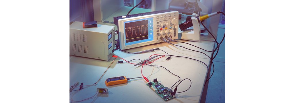
When testing, set the oscilloscope's TIME/DIV position to 10µS/div and the bandwidth to 20MHz. The peak-to-peak value of the output voltage displayed on the oscilloscope is the output ripple voltage (the peak-to-peak value, including glitches, is the ripple + noise value).
1) Adjust the input voltage of the DC regulated power supply to the nominal voltage and the output current to the rated current.
2) The ripple of a DC regulated power supply is generally specified in peak-to-peak terms. This is the primary inspection method.
The ripple and noise of a DC regulated power supply are AC components superimposed on the DC output voltage. Ripple and noise measurements are performed under rated load and room temperature. For switching AC/DC regulated power supplies, the output ripple voltage is a system of small pulses with high-frequency components. Therefore, it is generally measured in peak-to-peak terms rather than in effective mean square (RMS) terms. The measured value is specified in millivolt peak-to-peak terms (mVp-p). For example, if the peak-to-peak ripple of an AC/DC regulated power supply is 50mV, its RMS value is very low, only 5mV. However, whether it is suitable for use in a particular system requires further consideration.
Because the measured ripple contains high-frequency components, special measurement techniques are required to obtain accurate results. To measure all high-frequency harmonics within the ripple spike, an oscilloscope with a 20MHz bandwidth is generally required.
Secondly, when measuring ripple, extreme caution is required to avoid introducing erroneous signals into the test equipment. The probe ground clip must be removed during measurement, as it acts as an antenna in a high-frequency radiation field, picking up noise and interfering with the measurement. Using a probe with a grounding ring can eliminate this interference.
This method uses a 50Ω coaxial cable to measure the output ripple voltage of a DC regulated power supply. The coaxial cable is connected directly to the oscilloscope. To reduce noise, an aluminum or copper ground plane should be used during the measurement. The measured value should be 1/2 of the actual value.
Using a dual-stripe measurement method
Place the DC regulated power supply at least 25mm from a ground plane made of aluminum or copper. Connect the DC regulated power supply's output common terminal and AC input ground terminal directly to the ground plane. The ground wire should be thick and no longer than 50mm.
Use 16AWG copper wire to create a 300mm long twisted pair. Connect one end to the power output and the other end in parallel with a 47μF tantalum capacitor. Connect this to the oscilloscope. Keep the capacitor leads as short as possible, and be careful not to reverse the polarity. The oscilloscope probe's "ground lead" should be connected to the ground ring as closely as possible. The oscilloscope's bandwidth should be at least 50MHz, and the oscilloscope itself should be grounded.
Check the output noise (including peak-to-peak noise, telephone-weighted noise, broadband noise, and discrete noise).
Share our interesting knowledge and stories on social media


