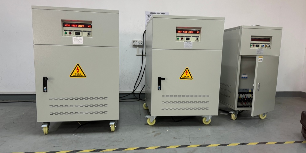
Introduction to Single-Phase Variable Frequency Power Supplies
The frequency converter in a single-phase variable frequency power supply is actually an inverter. It first converts the power to DC, and then uses electronic components to convert the DC power back to the power converter. Typically, more powerful inverters use SCRs and are equipped with a frequency converter. The frequency can be set at a fixed ratio. It is used to control the number of revolutions of a motor. The speed can also be set at a fixed ratio. Frequency converters are widely used for motor speed regulation. Speed control of communication motors is a key development direction in modern power transmission technology.
Introduction to Single-Phase Variable Frequency Power Supply Circuits
With the development of power electronics, frequency conversion technology has gradually matured from theory to practice. Frequency converters offer smooth speed regulation, a wide speed range, high efficiency, low starting current, stable operation, and significant energy savings. As a result, frequency converters for speed control have gradually replaced traditional speed control systems such as slip-type speed control, variable-pole speed control, and DC speed control, and are increasingly used in metallurgy, textiles, printing, air conditioning, construction, water supply, and other fields. It is generally divided into four major parts: the rectifier circuit, the smoothing circuit, the control circuit, and the inverter circuit.
1. Rectifier Circuit
The rectifier circuit converts the communication power supply into DC power. The rectifier circuit is usually a separate rectifier module.
2. Smoothing Circuit
The smoothing circuit combines a pulsating voltage with a frequency six times the rectifier power supply frequency and the rectified DC voltage. The pulsating current generated by the inverter also changes the DC voltage. Inductors and capacitors are used to control voltage fluctuations and absorb pulsating voltage (current). Because the DC portion of the power supply in a general-purpose inverter has edges in the main circuit, the rectifier is omitted and a simple capacitor filter smoothing circuit is selected.
3. Control Circuit
Today, inverters generally use a 16-bit or 32-bit microcontroller or DSP as the control core to achieve full digital control.
An inverter is a speed controller that can adjust the output voltage and frequency. The circuit that provides the control signal is called the main control circuit. The control circuit consists of a frequency and voltage calculation circuit, a main circuit voltage and current detection circuit, and a motor speed detection circuit. The control signals from the calculation circuit are sent to the control circuit and the converter motor maintenance circuit.Inverter control methods include speed control, shutdown control, and PID control.
4. Inverter Circuit
The inverter circuit, in contrast to the rectifier circuit, converts DC voltage to a voltage of the desired frequency and switches the upper and lower bridge power switches on and off within a specified timeframe. This enables three-phase voltages with a 120° phase difference to be achieved at output terminals U, V, and W.
Summary
For the main circuit of a single-phase variable-frequency power supply, an AC-DC-AC voltage-type variable-frequency circuit is selected. It primarily consists of rectification, filtering, and an inverter. The rectifier uses a single-phase bridge rectifier module for AC/DC conversion, the filter uses filter capacitors to stabilize the DC voltage, and the inverter uses a DIP-IPM intelligent power module for DC/AC conversion. The variable-frequency power supply control circuit regulates the frequency and amplitude of the power system's output signal to achieve variable voltage and frequency conversion. In order to ensure the safety and reliability of the system, overvoltage and undervoltage detection and maintenance circuits, optocoupler isolation drive circuits, auxiliary power conversion circuits, etc. are set up.
IDEALPLUISNG Power Expert:
We focus on the research and development, sales and services in the fields of DC-DC power modules, AC-DC rectifier modules, DC-AC inverters, AC power supplies, DC power supplies, LED power supplies, chargers, rectifier systems, etc., providing personalized, efficient, reliable and cost-effective power solutions for all walks of life.
Thank you for considering our services.


