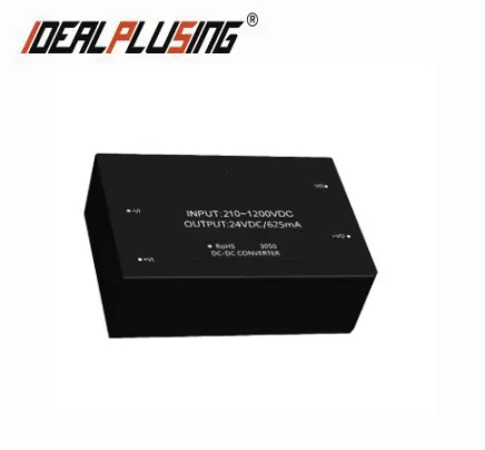

INTRODUCE
Ultra-wide input voltage DC power module is a power module that can accept a very wide range of DC voltage input. It is widely used in many fields.
FEATURES
lUltra - wide voltage Input : 210-1200 VDC
lHigh reliability, long life, industrial-grade design
lInput and output isolation
lInput reverse connection protection
lOutput overcurrent protection, output short circuit protection
lApplicable to various industrial and civil fields such as automation control and photovoltaic power generation
SPECIFICATIONS
Brand | IDEALPLUSING | ||||
Input Characteristics | |||||
Model | IPS05-V2S05 | ||||
Project | Condition | Minimum | Typical Value | Maximum | |
Input voltage range | DC input | 210VDC | 600VDC | 1200VDC | |
Inrush Current | 210VDC | - | 22A | - | |
Input undervoltage protection | Undervoltage protection point | - | 188VDC | - | |
Undervoltage release point | - | 200VDC | - | ||
Input reverse connection protection | have | ||||
Project | Condition | Typical value | Maximum | |
Output voltage accuracy | Single channel | ±1% | ±2% | |
Positive and negative dual paths, balanced output load*2 | Main Road:-Vo to Com | ±1% | ±2% | |
Auxiliary Road:Com to +Vo | ±5% | ±8% | ||
Isolation dual-channel, balanced output load | Main Road:Vo1 | ±1% | ±2% | |
Auxiliary Road:Vo2 | ±5% | ±8% | ||
Line Regulation |
Output full load | Single channel | ±0.5% | ±1% |
Dual main road | ±0.5% | ±1% | ||
Dual auxiliary road
| ±2.5%
| ±5%
| ||
Load Regulation | Single channel, 10%-100% load | ±0.5% | ±1% | |
Dual channels, 10%-100% load, balanced load | Dual main road | ±0.5% | ±1% | |
Dual auxiliary road | ±2.5% | ±5% | ||
Output ripple noise*1 |
20MHz bandwidth (peak-to-peak) | Single channel | 75mV | 150mV |
Dual main road | 75mV | 150mV | ||
Dual auxiliary road
| 150 mV | 300mV | ||
Short circuit protection | Can withstand long-term short circuit and self-recovery | |||
Output overcurrent protection
| ≥110%Io, self-recoverable | |||
Minimum load | - | - | ||
Start delay time | - | 6s | ||
Power-off retention time | 16ms | - | ||
Note: *1 Ripple and noise are tested using the parallel line test method (the oscilloscope probe is close to the test, and a 10μF hiIPS-frequency low-resistance electrolytic capacitor and a 0.1μF ceramic capacitor are connected in parallel at the close test point). *2. Balanced load means that the output load of the main circuit and the auxiliary circuit changes in the same proportion. | ||||
MODEL LIST
Model | Input voltage | Output Peak Voltage | Output Peak Current | Output Peak Power | Size (MM) |
IPS05-V2S05 |
210-1200VDC | 5VDC | 1000mA |
5W |
70.0*48.0*23.5mm (Plastic housing) |
IPS05-V2S12 | 12VDC | 420mA | |||
IPS05-V2S15 | 15VDC | 330mA | |||
IPS05-V2S24 | 24VDC | 210mA | |||
IPS10-V2S05 | 5VDC | 2000mA |
10W | ||
IPS10-V2S12 | 12VDC | 830mA | |||
IPS10-V2S15 | 15VDC | 670mA | |||
IPS10-V2S24 | 24VDC | 420mA | |||
IPS15-V2S05 | 5VDC | 3000A |
15W | ||
IPS15-V2S12 | 12VDC | 1250mA | |||
IPS15-V2S15 | 15VDC | 1000mA | |||
IPS15-V2S24 | 24VDC | 625mA | |||
IPS15-V2D05 | +5VDC | 1500mA | |||
IPS15-V2D12 | +12VDC | 625mA | |||
IPS15-V2D15 | +15VDC | 500mA | |||
IPS15-V2D24 | +24VDC | 312mA | |||
IPS15-V2E0505 | 5VDC | 2000mA | |||
IPS15-V2E0512 | 5VDC | 2000mA | |||
IPS15-V2E0524 | 5VDC | 2000mA | |||
IPS20-V2S05 | 5VDC | 4000mA | 20W |
72.0*50.0*23.5mm(Metal housing)
| |
IPS20-V2S12 | 12VDC | 1660mA | |||
IPS20-V2S15 | 15VDC | 1330mA | |||
IPS20-V2S24 | 24VDC | 830mA | |||
IPS25-V2S05 | 5VDC | 5000mA | 25W | ||
IPS25-V2S12 | 12VDC | 2080mA | |||
IPS25-V2S15 | 15VDC | 1660mA | |||
IPS25-V2S24 | 24VDC | 1040mA | |||
IPS25-V2D05 | +5VDC | 2500mA | |||
IPS25-V2D12 | +12VDC | 1040mA | |||
IPS25-V2D15 | +15VDC | 830mA | |||
IPS25-V2D24 | +24VDC | 520mA | |||
IPS25-V2E0505 | 5VDC | 3000mA | |||
IPS25-V2E0512 | 5VDC | 3000mA | |||
IPS25-V2E0524 | 5VDC | 3000mA |


