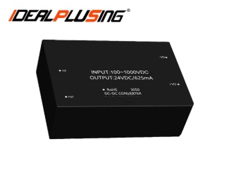

INTRODUCE
Ultra-wide input voltage DC power module is a power module that can accept a very wide range of DC voltage input. It is widely used in many fields.
FEATURES
l Ultra-wide voltage input:100-1000VDC
l 4000VDC high isolation withstand voltage
l High reliability, long life, industrial-grade design
l Input reverse connection protection
l Output over-current protection, output short-circuit protection
l Applicable to various industrial and civil fields such as automation control and photovoltaic power generation
SPECIFICATIONS
Project | Condition | Minimum | Typical Value | Maximum | |
Input voltage range | DC input | 100VDC | 500VDC | 1000VDC | |
Input Current |
500VDC | IPS05 | - | - | 17mA |
IPS10 | - | - | 32mA | ||
IPS15 | - | - | 46mA | ||
IPS20 | - | - | 61mA | ||
IPS25 | - | - | 74mA | ||
Inrush Current |
100VDC | IPS05、IPS10、IPS15 | - | 10A | - |
IPS20、IPS25 | - | 20A | - | ||
Input reverse connection protection | have | ||||
Project
| Condition | Minimum
| Typical value
| Maximum
| |
Single channel, output voltage accuracy | - | ±1% | ±2% | ||
Positive and negative dual-channel, output voltage accuracy | Positive and negative dual paths, balanced output load*2 | Main Road:-Vo to Com | - | ±1% | ±2% |
Auxiliary Road:Com to +Vo | - | ±5% | ±8% | ||
Isolation dual-circuit, output voltage accuracy | Isolation dual-channel, balanced output load | Main Road:Vo1 | - | ±1% | ±2% |
Auxiliary Road:Vo2 | - | ±5% | ±8% | ||
Line Regulation |
Output full load | Single channel | - | ±0.5% | ±1% |
Dual main road | - | ±0.5% | ±1% | ||
Dual auxiliary road
|
| ±2.5%
| ±5%
| ||
Load Regulation | Single channel, 10%-100% load | - | ±0.5% | ±1% | |
Dual channels, 10%-100% load, balanced load | Dual main road | - | ±0.5% | ±1% | |
Dual auxiliary road | - | ±2.5% | ±5% | ||
Load Regulation |
20MHz bandwidth (peak-to-peak) | Single channel | - | 75mV | 150mV |
Dual main road | - | 75mV | 150mV | ||
Dual auxiliary road
| - | 150 mV | 300mV | ||
Output ripple noise*1 | Can withstand long-term short circuit and self-recovery | ||||
Short circuit protection |
| ||||
Output overcurrent protection
| 0 | - | - | ||
Minimum load | - | 5s | - | ||
Start delay time | - | 16ms | - | ||
Operating temperature | -40℃ | - |
+70℃ | ||
Storage temperature | -40℃ | - | +105℃ | ||
Storage humidity | - | - | 95%RH | ||
Switching frequency | Input to output, test 60s, ≤5mA | 4000VDC | 65K HZ | - | |
Note: *1. Ripple and noise are tested using the parallel line test method. | |||||
*2. Balanced load means that the output load of the main circuit and the auxiliary circuit changes in the same proportion. | |||||
MODEL LIST
Model | Input voltage | Output Peak Voltage | Output Peak Current | Output Peak Power | Size (MM) | |
IPS05-V2S05-L |
100-1000VDC | 5VDC | 1000mA | 5W | 70.0*48.0*23.5mm (Plastic housing) | |
IPS05-V2S12-L | 12VDC | 420mA | ||||
IPS05-V2S15-L | 15VDC | 330mA | ||||
IPS05-V2S24-L | 24VDC | 210mA | ||||
IPS10-V2S05-L | 5VDC | 2000mA | 10W | |||
IPS10-V2S12-L | 12VDC | 830mA | ||||
IPS10-V2S15-L | 15VDC | 670mA | ||||
IPS10-V2S24-L | 24VDC | 420mA | ||||
IPS10-V2D05-L | +5VDC | 1000mA | ||||
IPS10-V2D12-L | +12VDC | 420mA | ||||
IPS10-V2D15-L | +15VDC | 330mA | ||||
IPS10-V2D24-L | +24VDC | 210mA | ||||
IPS10-V2E0505-L | 5VDC | 1800mA | ||||
IPS10-V2E0512-L | 5VDC | 1500mA | ||||
IPS10-V2E0524-L | 5VDC | 1000mA | 15W | |||
IPS15-V2S05-L | 5VDC | 3000mA | ||||
IPS15-V2S12-L | 12VDC | 1250mA | ||||
IPS15-V2S15-L | 15VDC | 1000mA | ||||
IPS15-V2S24-L | 24VDC | 625mA | ||||
IPS20-V2S05-L | 5VDC | 4000mA | 20W | 72.0*50.0*23.5mm (Metal housing) | ||
IPS20-V2S12-L | 12VDC | 1660mA | ||||
IPS20-V2S15-L | 15VDC | 1330mA | ||||
IPS20-V2S24-L | 24VDC | 830mA | ||||
IPS25-V2S05-L | 5VDC | 5000mA | 25W | |||
IPS25-V2S12-L | 12VDC | 2080mA | ||||
IPS25-V2S15-L | 15VDC | 1660mA | ||||
IPS25-V2S24-L | 24VDC | 1040mA | ||||


