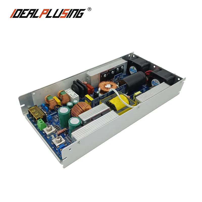

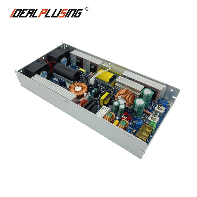
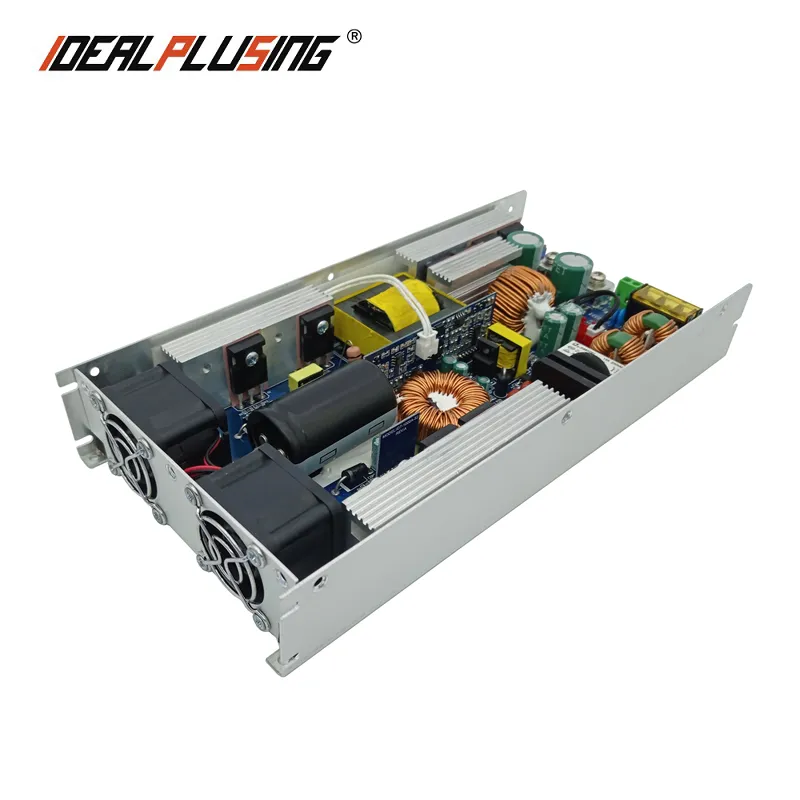
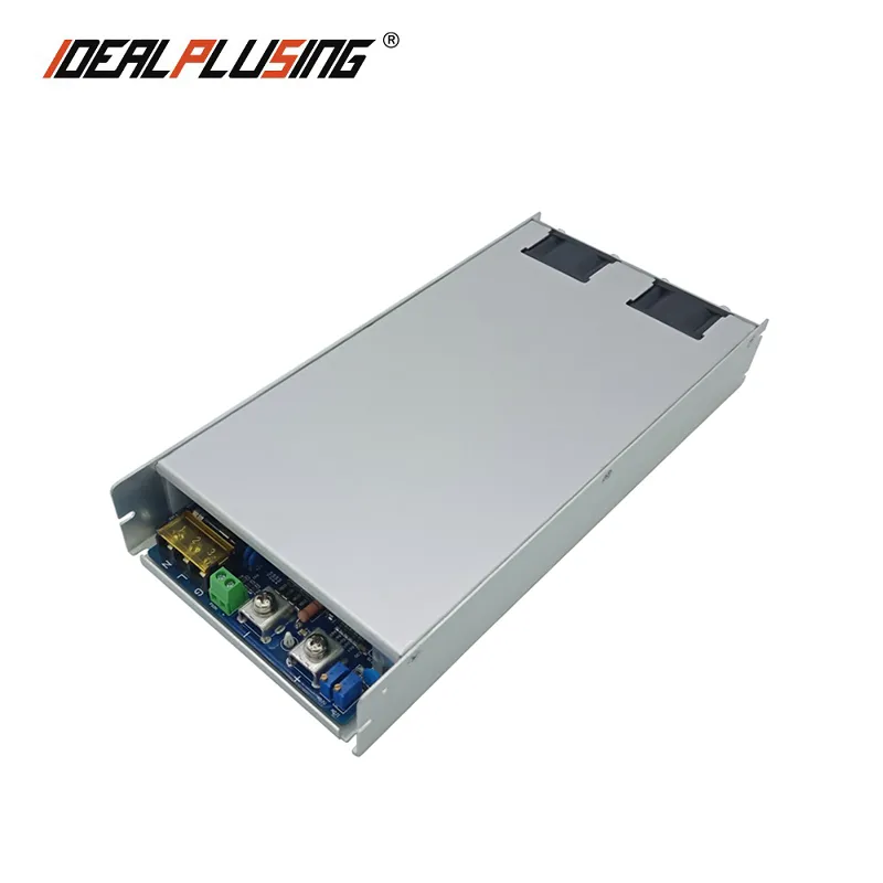
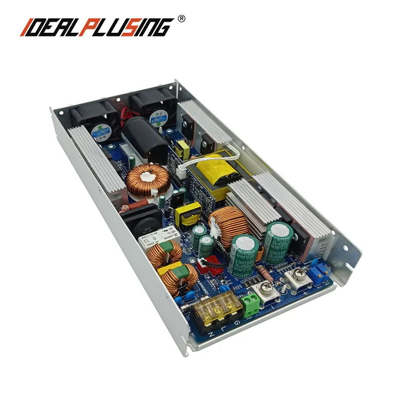
MODEL | IPS-PFC1000-12 | IPS-PFC1000-24 | IPS-PFC1000-36 | IPS-PFC1000-48 | IPS-PFC1000-54 | |
IPS-PFC1000-60 | IPS-PFC1000-72 | IPS-PFC1000-110 | IPS-PFC1000-150 | / | ||
OUTPUT | DC OUTPUT VOLTAGE | 12VDC | 24VDC | 36VDC | 48VDC | 54VDC |
60VDC | 72VDC | 110VDC | 150VDC | / | ||
RATED OUTPUT CURRENT | 75A | 42A | 28A | 21A | 18.5A | |
17A | 13.8A | 9A | 6.6A | / | ||
MAXIMUM OUTPUT CURRENT | 87.5A | 48A | 32A | 24A | 20A | |
19A | 16A | 10.4A | 7A | / | ||
RATED OUTPUT POWER | 900W | 1000W | 1000W | 1000W | 1000W | |
1000W | 1000W | 1000W | 1000W | / | ||
MAXIMUM OUTPUT POWER | 1050W | 1150W | 1150W | 1150W | 1080W | |
1150W | 1150W | 1150W | 1050W | / | ||
CONVERSION EFFICIENCY | 86% | 89% | 90.5% | 92% | 92% | |
92.5% | 92.5% | 93% | 93% | / | ||
RIPPLE (FULL LOAD) | 180mv | 200mv | 230mv | 250mv | 280mv | |
280mv | 300mv | 330mv | 350mv | / | ||
LINEAR ADJUSTMENT RATE | 1% | |||||
LOAD ADJUSTMENT RATE | ±1.5% | |||||
VOLTAGE STABILIZATION ACCURACY | ±3% | |||||
START UP, RISE TIME | 2s 100ms | |||||
HOLDING TIME | 10ms | |||||
OUTPUT WIRING MODE | M6 riveting terminal | |||||
INPUT | INPUT VOLTAGE | AC 110v-240v (wide voltage adaptive, no conversion required) | ||||
AC INPUT FREQUENCY | 50/60Hz | |||||
INPUT WIRING MODE | 3pin hb-9500 terminal with protective cover | |||||
INPUT CURRENT | Full load 1000W output, using 220VAC input, input current 5A | |||||
SURGE CURRENT | Cold start, 40A at 230V, 20A at 110V | |||||
FUNCTION |
PS-ON | PS-on terminal short circuit: no output voltage of power supply | ||||
OUTPUT VOLTAGE REGULATION | The output voltage can be adjusted in a full range. The adjv potentiometer can be adjusted | |||||
OUTPUT CURRENT REGULATION | The output current is adjustable in the whole process, and the ADJI potentiometer is | |||||
PROTECTION | OUTPUT HIGH VOLTAGE | When the output voltage reaches 125%, the output is turned off, | ||||
OUTPUT SHORT CIRCUIT | When the output terminal is short circuited, the power supply has no voltage output, and | |||||
OVER LOAD PROTECTION | The overload protection mode is constant current limiting mode, the locked output current | |||||
OVERHEATING PROTECTION | When the temperature of the heat sink of PWM transistor reaches 85 ℃, the output voltage | |||||
SECURITY | EMC STANDARD | Does not conform to EMC standards | ||||
INSULATION IMPEDANCE | I/P-O/P,I/P-FG,0/P-FG:100M Ohms /500VDC /25℃/70%RH | |||||
LEAKAGE CURRENT | ≤3.5MA/AC220V | |||||
WITHSTAND VOLTAGE | Input and output: 3000VAC Input and ground: 1500vac | |||||
SEISMIC BEHAVIOR | 10 ~ 500Hz, 2G 10 min / cycle, 60 min for each axis of XYZ | |||||
OTHER | HEAT DISSIPATION MODE | Fan heat dissipation (temperature control automatic speed regulating fan, double fan, | ||||
NOISE VALUE OF COOLING FAN | In the indoor environment of about 20-25 dB, when two fans rotate at full speed, about 37 | |||||
WORKING TEMPERATURE | -30-35℃, the power should be reduced when over temperature. Refer to the temperature | |||||
WEIGHT | Light and thin type 1.4kg (excluding package and accessories) | |||||
SIZE | Length 268mm * width 130mm * height 40mm | |||||
INSTALLATION HOLE POSITION | The long spacing is 260mm, and the width spacing is 120mm. The U-shaped groove and | |||||
Tips | 1.Pay attention to ventilation and heat dissipation when using. Do not install the power supply in a fully sealed box. There should be no object blocking the position of the heat dissipation outlet and fan air inlet of the power supply | |||||


