Introduction
Anyone who has debugged industrial power systems knows that unstable output voltage rarely originates from a single defective component. In most field cases, instability is the result of multiple factors interacting under real operating conditions. A converter that performs perfectly in the laboratory may oscillate after being installed inside an equipment cabinet with long wiring, inductive loads, and high ambient temperatures.
After supporting hundreds of industrial DC/DC converter applications—including battery energy storage, railway systems, telecommunications, and industrial automation—we have found that over 80% of voltage instability issues can be diagnosed without replacing the power module. The key is following a structured troubleshooting process rather than replacing components blindly.
1. Check the Input Source First
The fastest mistake engineers make is measuring only the converter output.
Always verify:
· Input voltage ripple
· Input cable voltage drop
· Source impedance
· Battery internal resistance
· Loose terminals
One energy storage project experienced ±6% output fluctuation. The converter was healthy—the battery voltage dropped nearly 9V during peak current because of an undersized cable.
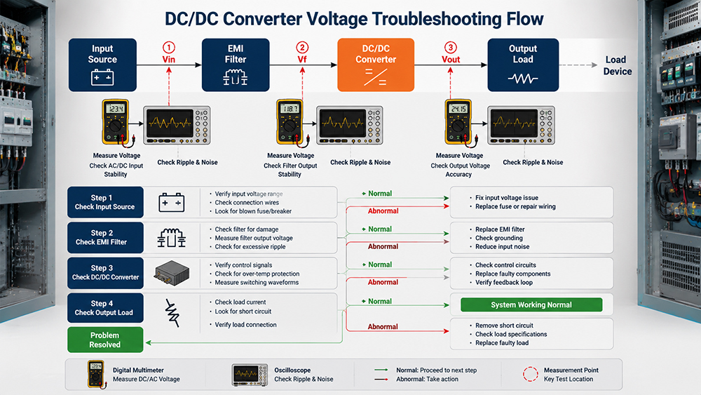
2. Feedback Circuit Problems Are More Common Than Controller Failures
In industrial environments, feedback wiring often causes instability.
Typical symptoms include:
· Output oscillation after cabinet installation
· Stable operation during no-load testing
· Voltage fluctuation only when high-current equipment starts
Project experience shows the following are frequent causes:
· Poor grounding
· Long sensing wires
· Oxidized connectors
· High-frequency noise coupling into the feedback circuit
Using twisted-pair remote sensing and star grounding often eliminates these problems without replacing hardware.
3. Load Characteristics Matter More Than Load Power
Many engineers only verify rated current.
Instead, check whether the load is:
· Capacitive
· Highly inductive
· Pulsed
· Regenerative
· Constant power
For example, a programmable electronic load switching from 10% to 90% load within milliseconds caused repeated voltage overshoot. The converter was operating correctly, but the compensation network required optimization for faster transient response.
Table 1. Typical Symptoms and Possible Causes
Symptom | Possible Cause | Recommended Action |
Periodic voltage ripple | Input instability | Check source and cable |
Random voltage fluctuation | Loose connector | Inspect terminals |
Voltage drop at heavy load | Cable loss | Increase cable size |
Oscillation after installation | EMI coupling | Improve grounding |
Voltage overshoot | Dynamic load | Optimize compensation |
4. Temperature Changes Shift Converter Performance
Many "intermittent" voltage issues are thermal problems.
Inspect:
· Transformer temperature
· MOSFET temperature
· Electrolytic capacitor ESR
· Fan airflow
· Ambient cabinet temperature
One mining project worked perfectly in the morning but became unstable every afternoon. Thermal imaging revealed electrolytic capacitors operating above 90°C, increasing ESR and reducing loop stability.
5. Don't Ignore EMI
Voltage instability sometimes originates outside the converter.
Common external interference sources include:
· Variable Frequency Drives (VFDs)
· Large motor switching
· Contactors
· High-current busbars
· Nearby inverters
Using differential probes together with an oscilloscope can quickly determine whether oscillation is genuine output instability or measurement noise.
Engineering Case
A 5 kW isolated DC/DC converter repeatedly failed customer acceptance because output voltage fluctuated by nearly 3%.
The customer suspected defective firmware.
Field investigation found:
· Remote sensing wires routed alongside motor cables
· Shared grounding between power and control circuits
· Missing shield termination
After rerouting the sensing cables, separating grounds, and properly terminating the cable shield, voltage fluctuation fell below 0.15%, with no hardware replacement required.
This project reinforced a practical lesson:
Most voltage instability originates from system integration rather than converter hardware.
Need a Custom Power Solution?
Many voltage instability problems originate from system-level design rather than the power supply itself.
IDEALPLUSING specializes in high-reliability industrial power conversion solutions, including isolated DC/DC converters, programmable DC power supplies, bidirectional converters, and customized high-voltage power systems.
Need a custom bidirectional isolated topology or facing a challenging voltage stability issue? Submit your electrical parameters to the IDEALPLUSING senior engineering team for a free technical evaluation and application recommendation.
Conclusion
Successful troubleshooting is about identifying the real source of instability rather than replacing components. A disciplined process—checking the input source, feedback path, load dynamics, thermal behavior, and EMI environment—can resolve most field problems efficiently. Experienced engineers rely on measurement, isolation, and verification instead of assumptions, reducing downtime and improving long-term system reliability.