
I. Visual and Mechanical Inspection (The First Step After Unpacking)
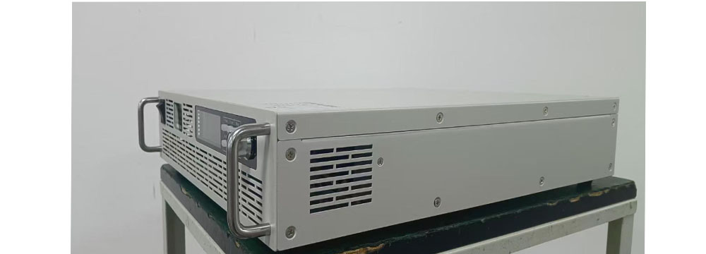
Before powering up a new unit, the first step is to inspect its mechanical structure. The unit features a standard 2U rack-mount chassis compatible with universal cabinet dimensions. It comes equipped with solid, bent-metal handles on both sides, making handling and installation effortless—whether the unit is placed temporarily on a workbench for testing or permanently mounted in a standard rack. The chassis design incorporates extensive matrix-style ventilation louvers and a honeycomb-patterned rear vent, creating a front-to-back airflow path. Unlike budget power supplies with single-side venting, this design ensures efficient heat dissipation during prolonged full-load operation, effectively preventing overheating shutdowns caused by heat buildup in enclosed cabinets.
The sheet metal joints are uniform, screw placements are precise, and the casing features an integrated shielding structure. In a laboratory environment where multiple instruments operate side-by-side, this design helps mitigate EMI (Electromagnetic Interference) generated by the power supply's switching transistors, preventing signal noise from contaminating data captured by nearby oscilloscopes or signal generators—a factor often overlooked in lab testing scenarios.
II. Rear Terminal Layout: Key Points for Standardized Wiring
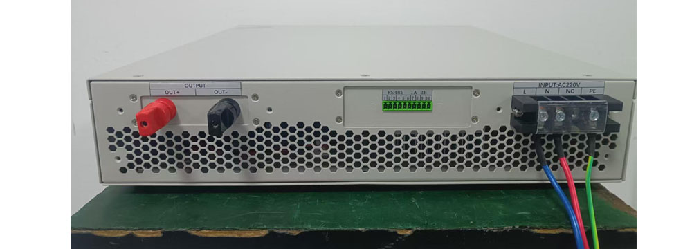
The rear panel is clearly divided into three distinct zones: AC input, DC power output, and communication interfaces. This physical separation of high-voltage (power) and low-voltage (signal) circuits naturally minimizes interference and simplifies the wiring process. 1. AC Mains Input (L/N/PE): Uses a terminal block connection; connect to single-phase 220V AC mains. The yellow-green ground wire must be securely connected to protective earth. A best practice here: for high-voltage/high-power DC power supplies, the ground wire must never be omitted or left floating. Proper grounding dissipates static charge from the chassis and provides a safety path in the event of internal insulation failure—a fundamental safety requirement for laboratory equipment. Ensure the red, blue, yellow, and green wires are firmly secured to prevent loosening due to heat generation during prolonged operation.
2. DC Power Output Terminals (OUT+, OUT-): Large brass binding posts accommodate load cables with various large cross-sectional areas. Apply moderate torque when tightening; do not overtighten and strip the threads. Strictly match positive and negative terminals to the load markings; never power on with reversed polarity. When testing capacitive loads, it is recommended to connect a discharge resistor in parallel at the output to bleed off residual voltage after power-off, preventing electric shock from accidental contact.
3. RS485 Communication Terminals: Standard bus interface compatible with the Modbus-RTU protocol. When debugging automated PC-based control or PLC-linked testing, simply connect the A and B signal lines using a twisted pair. Route communication lines separately—do not bundle them in parallel with high-power output cables—to avoid data packet loss caused by power ripple interference.
The wiring process is logically structured; even beginners can easily wire the unit by following the markings, thereby reducing the time spent troubleshooting during initial setup.
III. Front Panel Operation: Local Manual Debugging Workflow
The panel features an LCD screen, physical function buttons, and a rotary encoder—the standard configuration for offline laboratory debugging.
· Basic Operation Logic: Use "V-set" to define the output voltage and "I-set" to set the current limit. Values can be adjusted precisely using the rotary encoder, supporting both direct digital input and fine-tuning via the knob. Once settings are configured, press the ON/OFF button to activate the DC output. After test parameters stabilize, engage the "Lock" function to disable panel buttons and the knob, preventing accidental changes to test conditions. ·Automatic CV/CC Mode Switching: The power supply features an internal dual-closed-loop hardware circuit. It maintains Constant Voltage (CV) mode under no-load or resistive load conditions; when the load current reaches the preset limit, it automatically switches to Constant Current (CC) mode. When performing component surge or capacitor charging tests, there is no need for manual mode switching—the power supply adapts to operating conditions, significantly reducing the probability of device breakdown at the moment of power-up.
·Main Power Rocker Switch: A master power switch is located on the front panel, allowing the AC input to be cut off directly during maintenance or load replacement, ensuring safe and convenient operation.
IV. Practical Insights for Daily Laboratory Use
1.Standardized Power-Up Sequence: Connect AC mains and load wiring first → Turn on the master power switch → Set voltage and current thresholds → Enable high-voltage output. Follow the reverse order for shutdown (disable output first, then cut off master power) to prevent connecting or disconnecting load cables while the unit is live.
2.Protection Mechanism Performance: Equipped with four-fold hardware protection (over-voltage, over-current, short-circuit, and over-temperature). If a sample accidentally breaks down or shorts during testing, the power supply cuts off the output within milliseconds, preventing catastrophic failure or internal component damage and reducing the loss of test consumables.
3.Heat Dissipation and Maintenance: Dust accumulates in the honeycomb air intakes over time; it is recommended to periodically disconnect power and blow out dust from the air channels to ensure cooling efficiency and maintain long-term output accuracy.
4.Usage Scenarios: Use front-panel local controls for R&D exploratory testing; switch to RS485 remote control for batch burn-in testing or automated test platform setups, facilitating the implementation of semi-automated laboratory testing solutions.
For laboratory engineers, a high-quality programmable DC power supply is defined by more than just nominal voltage and current accuracy specifications. Factors such as chassis thermal design, intuitive panel layout, organized rear terminal arrangement, and user-friendly wiring logic directly impact daily debugging efficiency and testing safety. This record covers the routine acceptance, wiring, and setup of the new unit; future updates will include measured data on load ripple and temperature rise during prolonged full-load operation.