Introduction
Many engineers still ask, "Should I use an isolated converter?" After more than twenty years designing industrial power supplies, ESS, EV chargers, and telecom equipment, I've learned that the wrong topology rarely fails during prototype testing—it fails months later in the field.
The real engineering decision is not isolation versus efficiency. It is understanding where electrical stress, grounding, noise, and maintenance risks exist before selecting the topology.
1.When Isolation Becomes a Requirement
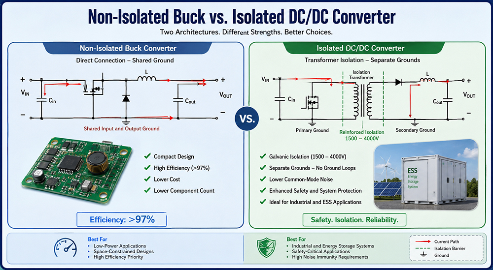
Battery energy storage, medical equipment, railway systems, and high-voltage DC applications generally require galvanic isolation. Isolation prevents ground loops, common-mode current, and fault propagation.
In one ESS project, a non-isolated converter powered the BMS auxiliary circuit. During surge testing, ground potential differences repeatedly damaged communication interfaces. Replacing it with an isolated converter completely solved the issue without redesigning the system.
2.When Non-Isolated Designs Are Better
When the input and output share a common ground reference and high conversion efficiency is a primary design requirement, non-isolated DC/DC converters generally remain the preferred engineering solution. Under these operating conditions, their simplified power conversion architecture provides both technical and economic advantages.
Industrial automation systems, robotic control platforms, LED driver applications, and embedded electronic systems all benefit from a reduced component count, a more compact PCB layout, and conversion efficiencies that typically exceed 97%. These characteristics contribute to improved power density, simplified system integration, and lower overall manufacturing costs.
Effective PCB layout and a well-designed grounding strategy are often more critical to achieving satisfactory electromagnetic compatibility (EMC) performance than the choice of converter topology itself. In many practical applications, careful PCB implementation has a greater influence on EMC compliance than the selected power conversion architecture.
3.Engineering Comparison
Parameter | Isolated | Non-Isolated |
Electrical Safety | ★★★★★ | ★★☆☆☆ |
Efficiency | 88–96% | 95–98% |
Common-mode Noise | Low | Higher |
PCB Complexity | High | Low |
Typical Applications | ESS, Medical, EV, Railway | Automation, Robotics, Embedded |
Initial Cost | Higher | Lower |
4.Common Failure Modes
Most field failures are not caused by efficiency.
Typical field issues include ground loop interference, transient surge-induced damage, excessive common-mode current, electromagnetic compatibility (EMC) failures, and inadequate isolation spacing. These failure mechanisms are among the most frequently encountered challenges in practical power conversion systems.
Rather than selecting a converter solely on the basis of electrical specifications, experienced engineers perform a comprehensive assessment of the grounding architecture, transient operating environment, maintenance accessibility, and applicable regulatory compliance requirements. This systematic evaluation significantly improves long-term system reliability and operational robustness.
Need a custom bidirectional isolated topology?
IDEALPLUSING provides customized DC/DC power solutions for energy storage systems, EV charging, industrial automation, and renewable energy applications.
Submit your electrical specifications to our senior engineering team for a free technical evaluation and topology recommendation.
Conclusion
There is no universally superior DC/DC converter topology. The right choice depends on safety, grounding strategy, EMC performance, reliability, and lifecycle cost. Selecting the correct architecture early can prevent years of field failures.