What is an adjustable switching power supply? An adjustable switching power supply is a power converter that adjusts the power supply of the device in the circuit by converting the voltage of the input power supply into the output voltage. Compared with a linear regulator, an adjustable switching power supply has higher efficiency and smaller size.
The advantages of an adjustable switching power supply are high efficiency, good reliability, small size and light weight. However, it also has some disadvantages, such as large output ripple and strong electromagnetic interference. Therefore, when using an adjustable switching power supply, attention should be paid to electromagnetic compatibility, temperature management and noise control.
Structure and principle of an adjustable switching power supply
The adjustable switching power supply includes components such as input filter capacitors, rectifier bridges, power switches, output filter inductors, output filter capacitors and feedback control circuits. The working principle is to switch the input voltage into high-frequency pulses through high-frequency switching devices (such as MOSFET, IGBT, etc.), transform and filter the voltage and current through components such as transformers and output filter circuits, and finally output the required voltage and current.
Specifically, the working process of the adjustable switching power supply is as follows.
Input filtering: The input voltage is filtered through the input filter capacitor to remove high-frequency noise in the power supply.Rectification: The filtered voltage converts AC into DC through a rectifier bridge.

Switch conversion: The rectified DC enters a high-frequency switching device, such as a MOSFET tube, to convert the voltage into a high-frequency pulse. Its switching frequency is usually above 20kHz, which can enable the switching device to switch at high speed and reduce power loss.
Transformer: The high-frequency pulse signal is transformed by the transformer to adjust the output voltage and current. The output of the transformer also needs to be filtered by a filter circuit to remove high-frequency noise and clutter.
Output filtering: The current output by the transformer is filtered by the output filter inductor and filter capacitor to remove high-frequency noise and clutter and obtain a smooth output current.

Feedback control: The adjustable switching power supply usually uses a feedback control circuit to keep the output voltage stable. The principle is to sample and compare the output voltage to obtain a feedback error signal, and then adjust the output voltage by controlling the duty cycle of the switching device to keep it stable.
Summary: The adjustable switching power supply converts the input voltage into a pulse signal through a high-frequency switching tube, and outputs a stable DC voltage after being processed by a transformer, a filter circuit and a voltage stabilizing circuit. The feedback control circuit can achieve precise adjustment of the output voltage to meet the needs of different circuit devices.
For example, we want to set the output of 12.6v1.8A:
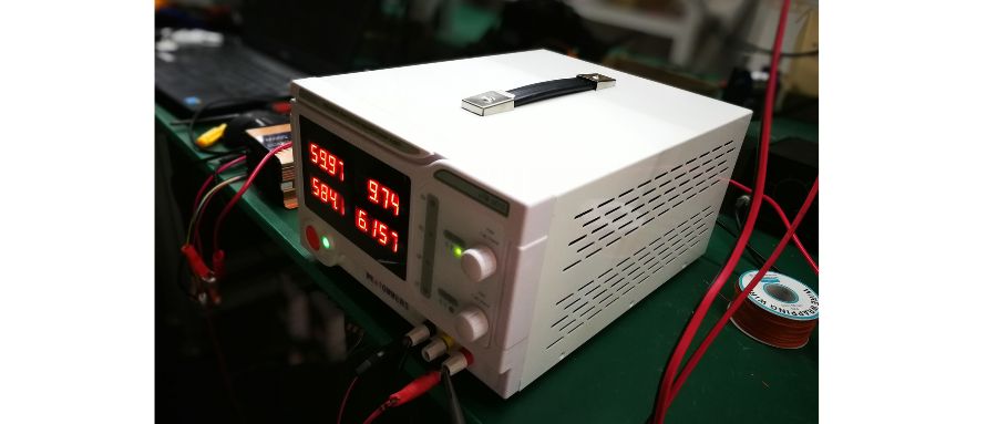
In the specific operation process, please turn on the power switch and test the no-load voltage first. The digital display and two buttons are used to display and adjust the output voltage value. One of the two knobs is a rough setting, and the other is a fine adjustment. Rotate the two knobs, and the voltage should be able to change continuously from 0 to the maximum value. After confirming that the voltage regulation function is normal, the current can be adjusted in the next step.
When adjusting the current, the output terminal must be set to short circuit. To avoid power failure, first reduce the voltage to about 2V (but it should not be reduced to 0, otherwise no current will be output), and then short-circuit the output terminal of the power supply. At this time, the voltage of the voltmeter drops sharply. Close to zero volts, the ammeter displays the current value. Then set the current to 1.8A by adjusting the two current regulators on the right. Then disconnect the positive and negative poles of the output connector to end the short-circuit state. At this point, the current disappears and the voltage returns to the state before adjustment.
The next step to adjust the tension is relatively simple. Just adjust the two rotary buttons to set the voltage to 12.6V.
If the current and voltage cannot be adjusted after following the above steps, it means that the power supply is faulty. It is common for the potentiometer to be excessively worn, which can be solved by replacing components with the same specifications. If there are other errors, it will become more complicated and can only be analyzed based on the specific situation.
Here, by the way, explain that this power supply has the conditions to achieve constant current or constant voltage. This is not a failure of the power supply function, but is determined by Ohm's law. For example, for the 12.6V and 1.8A listed above, when the load connected to the power supply is low power and the current does not reach 1.8A, the power supply output is in a constant voltage state. The voltage from 0 to 1.8A and 12.6V remains constant, and the current changes with the load, but the constant current cannot be reached.

If we want to further increase the output voltage, you will find that the voltage cannot be increased when the current reaches 1.8A. Because only then does the power supply enter a constant current state.
However, when the charging power increases, the current will exceed 1.8A, for example, greater than or equal to 1.8A. By connecting a high-performance 6Ω resistor. According to Ohm's law U/R = 1, 12.6 V ÷ 6Ω = 2.1 A, because the current is set to 1.8 A, the output voltage of the power supply becomes active at 10, 8 V (1.8 A Ⅹ 6Ω). Reduced to meet the set current requirements. This shows that it is impossible to obtain constant current and constant voltage at the same time. When the current is constant, the pressure is not constant, and when the pressure is constant, the current is not constant.
This constant current function is very useful when measuring LED light sources. For example, when measuring a 1W lamp bead, the current can be set to 0.3A and the voltage is 4-5V (slightly higher than ⅤF). If the voltmeter reads 3.25 V, this is the VF value of the lamp bead. It is convenient to classify and filter light sources or lamp beads.
When the 220V power supply is normal, the current is zero, indicating a power failure. Usually, the adjustable potentiometer is adjusted for a long time, which may cause poor contact. At this time, you can replace it with a new one and try again. If it still doesn't work, there is a problem with the voltage regulator and you can adjust the voltage stabilization circuit.


