The working principle of DC-DC converter can be divided into three categories: boost DC-DC converter, buck DC-DC converter and buck-boost DC-DC converter
DC-DC converter is a device that converts DC voltage or current into high-frequency square wave voltage or current. Its working principle is to convert the input DC power into high-frequency signal through control chips, inductors, diodes, transistors and capacitors, and then convert the high-frequency signal into the required DC output voltage through rectifiers. The main function of DC-DC converter is to convert electrical energy into electrical energy to meet the power supply requirements of different devices.
The working principle of DC-DC converter can be divided into three categories: boost DC-DC converter, buck DC-DC converter and buck-boost DCDC converter. Among them, PWM control DC-DC converter has high efficiency and small output voltage ripple and noise, so it is widely used in practical applications.

It should be noted that DC-DC converter will generate certain electromagnetic interference during its operation, so it is necessary to consider its interference suppression and the realization of filtering circuits when designing and using it. In addition, different types of DC-DC converters also have differences in circuit topology, control mode and output characteristics, and it is necessary to select the appropriate type according to actual needs.
In short, DC-DC converter plays an important role in electronic devices. Its working principle is to convert DC power into the required DC output voltage by controlling circuit elements to meet the power supply requirements of different devices. DC-DC converter circuit diagram Working principle of boost boost DC-DC converter Boost boost DC-DC converter is a commonly used power management circuit that can convert a lower DC input voltage into a higher DC output voltage. Its working principle is mainly based on the energy storage and release principle of the inductor and the switch control of the switch tube. Below we will analyze the circuit diagram and working principle of the boost boost DC-DC converter in detail.
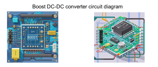
Boost DC-DC converter circuit diagram
The circuit diagram of the Boost DC-DC converter mainly includes input voltage, inductor, switch tube, diode and output voltage. The specific circuit diagram is as follows:

Working Principle of Boost DC-DC Converter
1. Working Process
The working process of Boost DC-DC converter is mainly divided into three stages: charging stage, energy storage stage and discharge stage.
(1) Charging stage: When the switch tube is in the on state, the input voltage charges the capacitor through the inductor and the switch tube, and the inductor absorbs energy at this time.
(2) Energy storage stage: When the switch tube is in the off state, the input voltage and the inductor jointly charge the output capacitor. At this time, the inductor releases the energy absorbed before to maintain the stability of the output voltage.
(3) Discharge stage: When the switch tube is turned on again, the inductor charges the output capacitor through the switch tube and the diode, and the inductor absorbs energy again.
2. Working Principle Analysis
From the above working process, it can be seen that the working principle of the Boost DC-DC converter is mainly based on the energy storage and release principle of the inductor and the switch control of the switch tube. In the charging stage, the inductor absorbs energy and stores magnetic field energy, and the current gradually increases; in the energy storage stage, the inductor releases the energy absorbed before to maintain the stability of the output voltage; in the discharge stage, the inductor absorbs energy again to prepare for the next charging stage. The switch control of the switch tube ensures the energy transfer and conversion efficiency.


