Definition
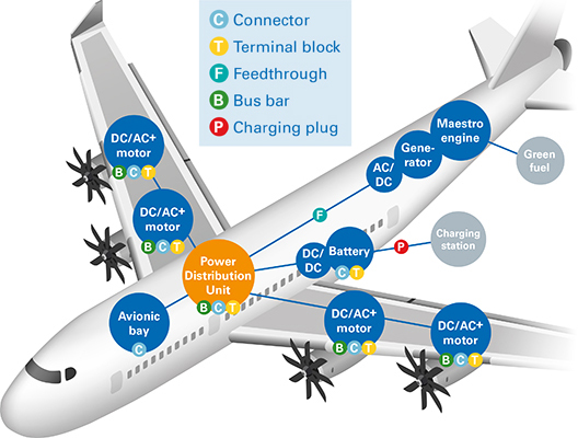
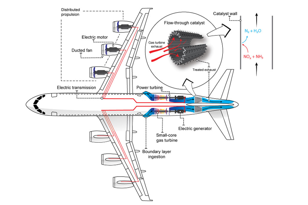
An aircraft electrical system is a self-contained network of components that generate, transmit, distribute, utilize, and store electrical energy.
General Description
An electrical system is an integral and essential component of all but the most simple of aircraft designs. The electrical system capacity and complexity varies tremendously between a light, piston-powered, single-engine general aviation aircraft and a modern, multi-engine commercial jet aircraft. However, the electrical system for aircraft at both ends of the complexity spectrum share many of the same basic components.
All aircraft electrical systems have components with the ability to generate electricity. Depending upon the aircraft, generators or alternators are used to produce electricity. These are usually engine-driven but may also be powered by an APU, a hydraulic motor, or a Ram Air Turbine (RAT). Generator output is normally 115-120V/400HZ AC, 28V DC or 14V DC. Power from the generator may be used without modification or it may be routed through transformers, rectifiers or inverters to change the voltage or type of current.
The generator output will normally be directed to one or more distribution busses. Individual components are powered from the bus with circuit protection in the form of a circuit breaker or fuse incorporated into the wiring.
The generator output is also used to charge the aircraft battery(s). Batteries are usually either of the lead-acid or NICAD types, but lithium batteries are becoming more and more common. They are used for both aircraft startup and as an emergency source of power in the event of a generation or distribution system failure.
Basic Aircraft Electrical Systems
Some very simple single-engine aircraft do not have an electrical system installed. The piston engine is equiped with a magneto ignition system, which is self-powering, and the fuel tank is situated so it will gravity feed the engine. The aircraft is started by means of a flywheel and crank arrangement or by "hand-propping" the engine.
If an electric starter, lights, electric flight instruments, navigation aids or radios are desired, an electrical system becomes a necessity. In most cases, the system will be DC-powered using a single distribution bus, a single battery, and a single engine-driven generator or alternator. Provisions, in the form of an on/off switch, will be incorporated to allow the battery to be isolated from the bus and for the generator/alternator to be isolated from the bus. An ammeter, loadmeter or warning light will also be incorporated to provide an indication of charging system failure. Electrical components will be wired to the bus-bar, incorporating either circuit breakers or fuses for circuit protection. Provisions may be provided to allow an external power source such as an extra battery or a Ground Power Unit (GPU) to be connected to assist with the engine start or to provide power whilst the engine is not running.

Advanced Aircraft Electrical Systems
More sophisticated electrical systems are usually multiple voltage systems using a combination of AC and DC buses to power various aircraft components. Primary power generation is normally AC with one or more Transformer Rectifier Unit (TRU) providing conversion to DC voltage to power the DC busses. Secondary AC generation from an APU is usually provided for use on the ground when engines are not running and for airborne use in the event of component failure. Tertiary generation in the form of a hydraulic motor or a RAT may also be incorporated into the system to provide redundancy in the event of multiple failures. Essential AC and DC components are wired to specific busses and special provisions are made to provide power to these busses under almost all failure situations. In the event that all AC power generation is lost, a static Inverter is included in the system so the Essential AC bus can be powered from the aircraft batteries.
Robust system monitoring and failure warning provisions are incorporated into the electrical system and these are presented to the pilots when appropriate. Warnings may include, but are not limited to, generator malfuntion/failure, TRU failure, battery failure, bus fault/failure and circuit breaker monitoring. The manufacturer will also provide detailed electrical system isolation procedures to be utilized in the event of an electrical fire.
In compliance with applicable regulations, components such as Standby Flight Instruments and Aircraft Emergency Floor Path Illumination have their own backup power supplies and will function even in the event of a complete electrical system failure.
Provisions are virtually always provided for connecting the aircraft electrical system to a fixed or mobile Ground Power Unit (GPU).


