


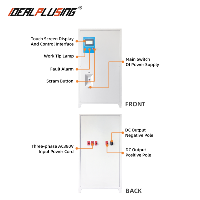
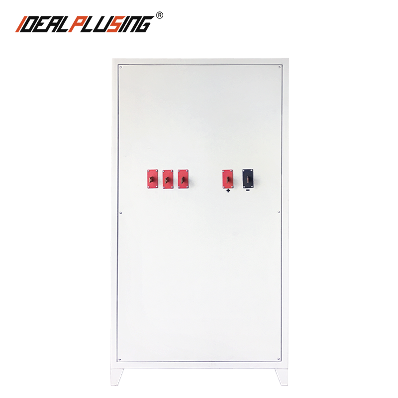
AC Input | 3-Phase 600V AC ±10% 50/60Hz |
Model | IPS-ATDD1502300 |
Output Voltage | 0-150VDC |
Output Current | 0-2300A |
Output Power | 276KW |
Protection Functions | Multiple protection functions, including overvoltage, overcurrent, undervoltage, short circuit, phase loss, and overheating. |
Control Method | PLC Analog Control Isolation Module |
Control Method | RS485 Serial Port / TCP Network Port Control Function |
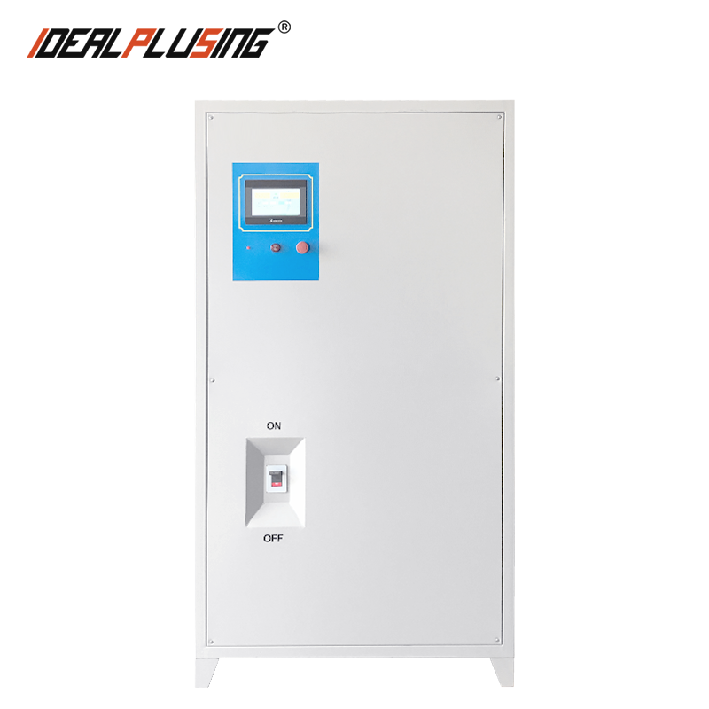
Display & Operation | 7 inch color touchscreen with real time V/I monitoring. |
Operation: Touch + Local/Remote control. | |
Communication | RS 485 (Modbus RTU) + CANSupports remote read/write of all major parameters. |
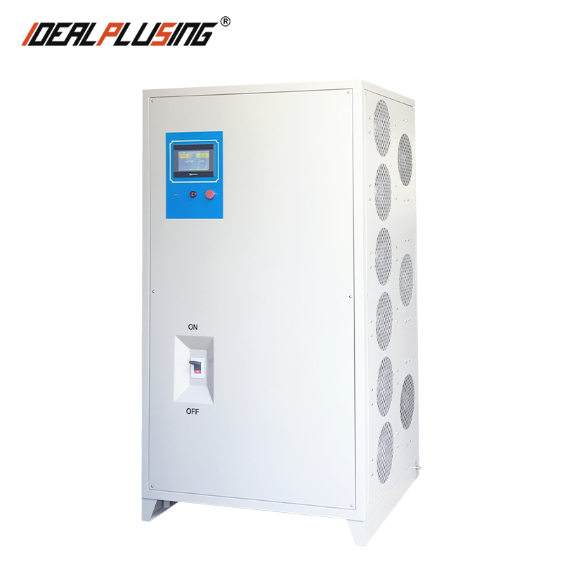
Cooling | Water Cooling |
Dimensions (HWL) | 1200 * 630 * 1200 mm |
Weight | Net: 720KG / Gross: 815 KG |
Environment | Op: 20℃~45℃, 10%~95% RHSt: 20℃~70℃, 10%~95% RH |
Notes | 1. Product Structure: Composed of a primary rectification unit, an inverter unit (IGBT), a high-frequency transformer, a secondary rectification system, a drive and control system, a protection system, a communication system, a cooling system, and other components. |
Design Operating Conditions | |
1 | Ambient Temperature: -20°C to 45°C |
2 | Relative Humidity: 10%–95% |
3 | Altitude: ≤ 1500 m |
4 | Vertical Tilt: ≤5° |
5 | The equipment is installed indoors. |
6 | No severe vibration or shock. |
7 | The air must be free from excessive dust and explosive gases, and the environment must be free from highly corrosive gases. |
Features | |
1 | Product Structure: Composed of a primary rectification unit, an inverter unit (IGBT), a high-frequency transformer, a secondary rectification system, a drive and control system, a protection system, a communication system, a cooling system, and other components. |
2 | Application Fields: Wastewater treatment, electroplating, electrolysis, electrochemistry, electrophoretic painting, oxidation, rare earth smelting, testing, and other application areas. |
3 | Parallel Operation Architecture: Utilizing CAN communication, the current of the slave unit is synchronized with that of the master unit. The chassis is designed with reserved space to accommodate future expansion, allowing for an increase in maximum current capacity through the subsequent addition of modules. For every 18 kW increase in output power, one 300A/1700V IGBT is added; for every 36 kW increase, one 300A rectifier bridge is added; for every 12 kW increase, one magnetic core is added; and for every 100A increase in output current, one diode is added. |
Control Method | |
1. Local Unit Remote Control Box Functions | Voltage and Current Display |
Constant Voltage/Constant Current Mode Switching | |
Timer/Amp-Hour Meter – Alarm | |
Voltage/Current-Time Parameter Settings | |


